Variable resistors are resistors that change resistance from zero to a certain maximum value. They are commonly used as volume controls and voltage regulators.

Variable resistors can be categorized into three types:
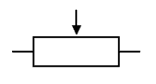
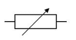
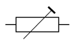
Symbols for Variable Resistors
Potentiometers
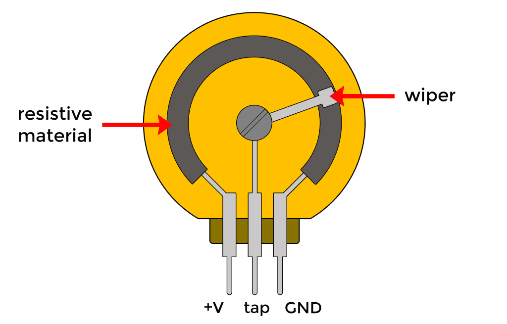
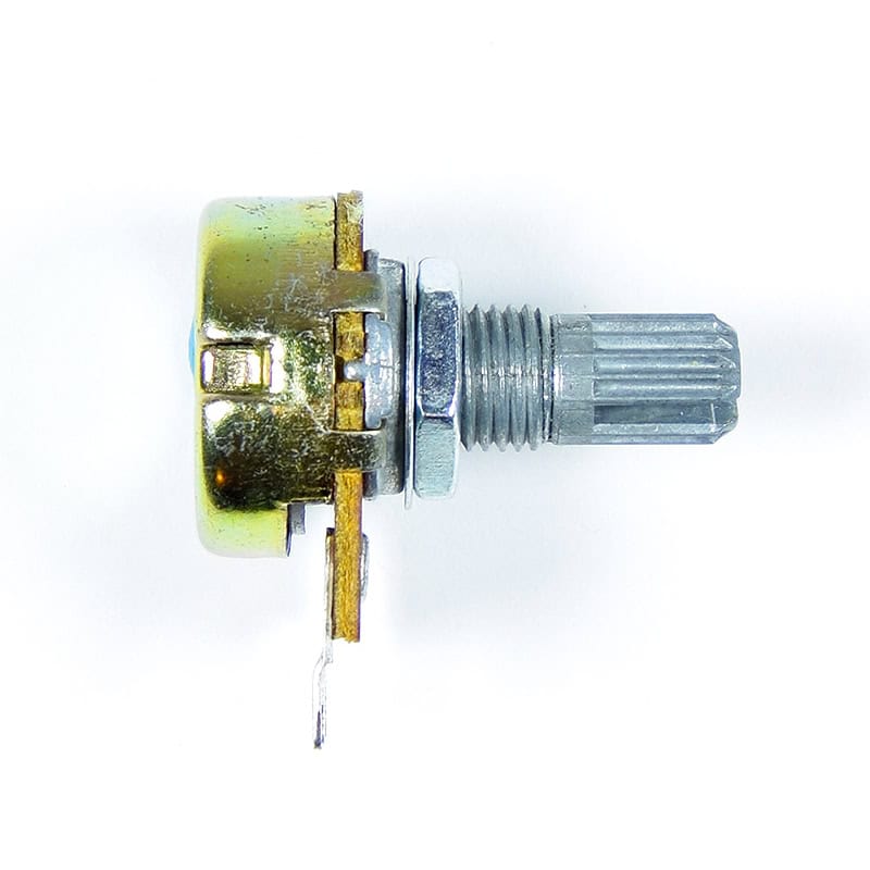
Potentiometers are used to vary the resistance in a circuit by turning a rotary knob. Potentiometers have three pins. Between the two side pins, there is a strip of resistive material and this material creates resistance. The middle pin is the wiper. This wiper connection is somewhere on the strip between the two ends. You can move the point where the wiper connects to the resistive material by turning the shaft of the potentiometer. When moving the wiper to the left side, there is a decrease in resistance between the middle pin and the left pin. Then, the resistance between the middle pin and the right pin increases upon moving the wiper to the left side.
Types of Potentiometers
- Rotary Potentiometers – the most common type of potentiometer. They use a rotary knob to move the wiper around the resistive material.
- Linear Potentiometers – consist of a linear slider that controls the position of the wiper along the resistive material.
Potentiometers are Like Voltage Dividers
A voltage divider is a simple circuit that can be used to reduce the voltage in a circuit. The output voltage depends on the ratio of two resistors connected in series. The output voltage is taken from a point between the two resistors. To calculate the output voltage of a voltage divider, use the Voltage Divider Equation below:
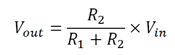
R1 is the resistor closest to the input voltage, R2 is the resistor closest to ground, Vin is the input voltage, and Vout is the output voltage.
Potentiometers are basically just adjustable voltage dividers.
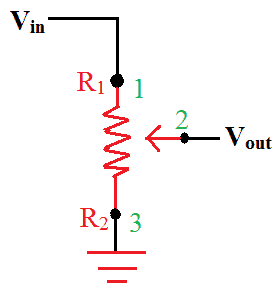
Potentiometer Schematic Symbol
Internal to the potentiometer is a single resistor and a wiper that cuts the resistor into two and moves to adjust the ratio between both halves. Externally, there are usually three pins: two pins connect to each end of the resistor, while the third connects to the potentiometer’s wiper. If the two outside pins are connected to a voltage, the output (Vout at the middle pin) will mimic a voltage divider. If the potentiometer will turn all the way in one direction, the voltage may be zero. And if it turns to the other side, the output voltage approaches the input and a wiper in the middle position means the output voltage will be half of the input.
Wiring a Potentiometer
- Begin by identifying the three terminals on the potentiometer. Position it with the shaft facing up and the three terminals are facing towards you. In this position, you can easily identify the terminals from left to right as terminal 1, 2, and 3. Ground the first terminal of the potentiometer.
- In this application, terminal 1 will provide the grounding. To do this, solder both ends of the wire to the terminal and chassis of the electrical component respectively. Measure and cut the length of the wire you will need to connect the terminal to a convenient location on the chassis and solder both ends of the wire to terminal and to the component’s chassis. This will ground the potentiometer. And it can be turned all the way to zero at the minimum position.
- Wire the second terminal to the circuit’s output to create the potentiometer’s input. The input line from the circuit should connect to it. Solder this connection just like the previous one.
- Wire terminal 3 to the circuit’s input since terminal 3 is the potentiometer’s output. Solder the wire just like in the first 2 terminals.
- After wiring, test using a voltmeter. Connect the voltmeter’s leads to the input and output terminals of the potentiometer and turn on the shaft. Turning the shaft clockwise or counterclockwise can adjust the signal on your device.
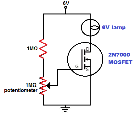
Example circuit of a light dimmer using a potentiometer and a MOSFET transistor
Digital Potentiometers
A digital potentiometer is a type of variable resistor that uses digital signals instead of mechanical motion to change its resistance. Digital potentiometers change resistance in discrete steps depending on the digital signal sent to it. They’re great for environments where vibration, dust, or moisture would gum up the shaft of a mechanical potentiometer.
Here are some digital potentiometers that are popular with electronics hobbyists:
The MPC41/42 family of digital potentiometers from Microchip are also fairly common:
- MCP4131 – 129 resistance points, available in 5kΩ, 10kΩ, 50kΩ and 100kΩ, operating voltage of 1.8V to 5.5V, controlled with SPI
- MCP42010 – 256 resistance points, available in 10kΩ, 50kΩ, and 100kΩ, operating voltage of 2.7V to 5.5V, controlled with SPI
Hope this article has given you some perspective on how to use variable resistors in your next electronics project! Feel free to leave a comment below if you have questions about anything…

Potentiometers
Potentiometers are used to measurePotentiometers cannot measure. What is the electromagnetic field of a cell?? the electromagnetic field of a cell. It is a three-terminal resistor with a variable or moving contact that divides a voltage into two parts. It has a fixed resistance track with connections at both ends and a sliding contact which is called a wiper. The wiper moves along this track by turning the spindle. If either of the connections and wiper is used, it behaves as a variable resistor or rheostat. If the wiper is not used, then it will offer fixed resistance across the two connections and they are specified by their fixed value resistance.
Potentiometers have three pins. Between the two side pins, there is a strip of resistive material and this material creates resistance. The middle pin is the wiper. This wiper connection is somewhere on the strip between the two ends. You can move the point where the wiper connects to the resistive material by turning the shaft of the potentiometer. When moving the wiper to the left side, left side with reference to where?there is a decrease in resistance between the middle pin and the left pin. Then, the resistance between the middle pin and the right pin increases upon moving the wiper to the left side.
Two Types of Potentiometer
Rotary Potentiometer (Rotary Knob) is the most common potentiometer. It uses a rotary motion to move the slider around a curved track. It has contacts usually at the end of the track where a part of the circle is missing.
Linear Potentiometer (Slider) consists of slider controls that slide in a linear fashion. It produces a resistance output that varies according to the position of a slider.
Voltage Divider and Potentiometers
A voltage divider is a simple circuit that converts a large voltage into a smaller one. No it doesn’t the voltage is always theeIt turns input voltage to a smaller voltage based on the ratio of the two resistors through distributing input voltage to the components of the divider. It is commonly used to supply a voltage different from an available battery or power supply. In determining the output voltage of a divider circuit, use the Voltage Divider Equation below:
where R1 is the resistor closest to the input voltage ( Vin), R2 is the resistor closest to ground, Vin is the input voltage and Vout is the output voltage across R2.
Voltage divider circuits are very common and used in many applications. One of these is in potentiometers. It is used to create adjustable voltage dividers.
Potentiometer Schematic Symbol
Referring to the diagram above, Pins 1 and 3 are the ends of the resistor, while Pin 2 connects to the wiper.
Internal to the potentiometer is a single resistor and a wiper that cuts the resistor into two and moves to adjust the ratio between both halves. Externally, there are usually three pins: two pins connect to each end of the resistor, while the third connects to the potentiometer’s wiper. If the two outside pins are connected to a voltage, the output (Vout at the middle pin) will mimic a voltage divider. If the potentiometer will turn all the way in one direction, the voltage may be zero. And if it turns to the other side, the output voltage approaches the input and a wiper in the middle position means the output voltage will be half of the input.
Wiring a Potentiometer What about log and antilog potentiometers, (volume controls)
Begin by identifying the three terminals on the potentiometer. Position it so that the shaft is facing towards the ceiling and the three terminals are facing towards you. In this position, you can easily identify the terminals from left to right as terminal 1, 2, and 3. Ground the first terminal of the potentiometer.
In this application, terminal 1 will provide the grounding. To do this, solder both ends of the wire to the terminal and chassis of the electrical component respectively. Measure and cut the length of the wire you will need to connect the terminal to a convenient location on the chassis and solder both ends of the wire to terminal and to the component’s chassis. This will ground the potentiometer. And it can be turned all the way to zero at the minimum position.
Wire the second terminal to the circuit’s output to create the potentiometer’s input. The input line from the circuit should connect to it. Solder this connection just like the previous one.
Wire terminal 3 to the circuit’s input since terminal 3 is the potentiometer’s output. Solder the wire just like in the first 2 terminals.
After wiring, test using a voltmeter. Connect the voltmeter’s leads to the input and output terminals of the potentiometer and turn on the shaft. Turning the shaft clockwise or counterclockwise can adjust the signal on your device.You talk about voltage then change to signal. All in all a confusing paragraph
Great article! The first section is very readable, but the second is confusing!