Electronic counters are widely used in digital electronics to record the number of times an event has occurred. They can store or output the numbers they have recorded. Counters are also referred to as timers.

Aside from counting, counters are also used for measuring frequency and time. Counters are now being used in a lot of applications such as frequency counters, digital clocks, analog-to-digital converters, frequency divider circuits and electronic device timers.
We can also find these inside the electronic devices we use at home. Microwave ovens and washing machines use counters to keep track of the time elapsed. Counters are also used in counting people entering and leaving a stadium or an auditorium.
Types of Counters
There are different types of counters for different applications. The two most common types are the synchronous counters and asynchronous counters.
Synchronous Counters
Synchronous counters are counters that use clock signal to change their transition. This means that synchronous counters depend on clock input to change state values. Flip flops, which are electronic circuits used to store binary data, in synchronous counters are triggered by the same clock signal.
Synchronous counters are very simple in design. All the flip flops are interconnected and driven by the same clock signal. The state output of the preceding flip flop determines the state change of the succeeding flip flop. Since the flip flops work synchronously, the synchronous counters do not require settling. There is a required number of logic gates to implement the synchronous counters and the operation is fast.
Unlike the asynchronous counter, the synchronous counter has one global clock which drives each flip flop so output changes in parallel. An advantage of synchronous counters over asynchronous counters is that it can operate on a higher frequency as it does not have cumulative delay from the clock.
Asynchronous Counters
Asynchronous counters transition without having to depend on the clock signal input. For these counters, the first flip flop is connected to the external clock signal, and the rest are clocked by the state outputs (Q & Q’) of the previous flip flop. For this reason, asynchronous counters are also called ripple counters. It uses a smaller number of logic gates and its operation is very slow compared to synchronous counters.
This counter will alternate between 0 to 1 and 1 to 0 for every cycle. Notice that this creates a new clock with a 50% duty cycle at exactly half the frequency of the input clock. You can continue to add additional flip flops, always inverting the output to its own input, and using the output from the previous flip flop as the clock signal. The result is called a ripple counter, which can count to (2n)-1, where n is the number of bits (flip-flop stages) in the counter.
Ripple counters suffer from unstable outputs as the overflow “ripples” from stage to stage. But they are useful in applications such as dividers for clock signals, where the instantaneous count is unimportant, but the division ratio overall is. To clarify this, a one-bit counter is equivalent to a ciruit that’s been divided by two; the output frequency is exactly half of the input when fed with a regular train of clock pulses. The use of flip flop outputs as clocks lead to timing skew between the count data bits, making this ripple technique incompatible with normal synchronous circuit design styles.
How Counters Work
For synchronous counters, the clock input across all the flip flops use the same source and create the same clock signal at the same time. A 4-bit synchronous up counter can count from 0 and increments or counts upwards to 15 and then start a new counting cycle after getting reset. There is no propagation delay in this counter because, again, all flip flops here are in parallel clock source. The clock triggers all the counters at the same time.
Some of the applications for synchronous counters include digital watch, digital clock, alarm systems, pulse generators, machine motion control, among others.
For asynchronous counters, as the count depends on clock signal, changing state bits are provided as the clock signal to the subsequent flip flops. The flip flops are serially connected together. The clock pulse ripples through the counter.
Some of the applications for asynchronous counters include low noise emission and low power applications, frequency dividers and etc.
Counter IC 4520 Pin Diagram
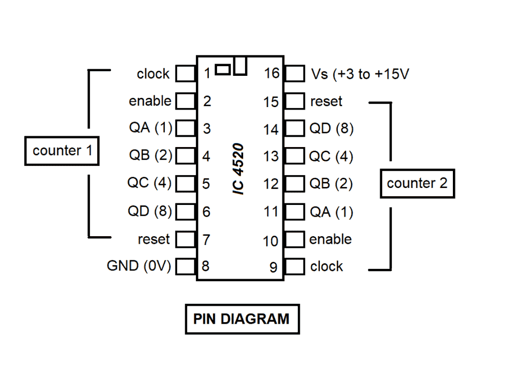
There are many different types of counter ICs available. In choosing which counter IC to use, you must consider the counting range required for your application. One example of a popular counter IC is the IC 4520. The decoding for this counter IC can be done on an external circuit. The range for IC 4520 is 0-15.
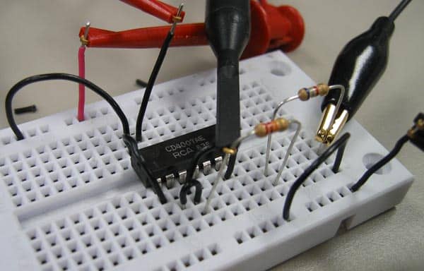
IC 4520 is a dual counter. Internally, it has two separate synchronous identical counters. The two counters can be used independently so you can use any of the two or both of them at the same time. This IC counter is sensitive to static so avoid touching a pin (with your clothes, for example) while charged with static electricity because it may damage your IC. Also, ICs should be left in their protective packaging until you are ready to use them.
Normally, a clock signal is connected to the clock input with the enable input held high. Counting advances as the clock signal becomes high (on the rising edge). For normal operation, the reset input should be low to make it high and to reset the counter to zero (0000, QA-QD low). Counting to less than the maximum (9 or 15) can be set by connecting the appropriate output/s to the reset input using an AND gate. For example, to count 0 to 8, connect QA (1) and QD (8) to reset using an AND gate.
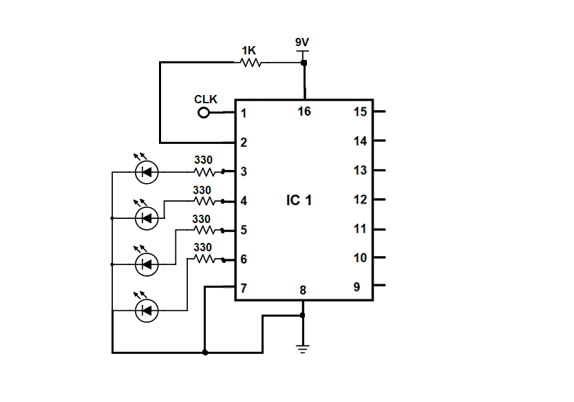
Counter IC 4520 Schematic Diagram
Thanks for reading and be sure to leave a comment below if you have questions about anything!