FM radio is transmitted with a process called frequency modulation. With frequency modulation, the audio signal is modulated (varied) by a high-frequency carrier signal. FM radio signals are transmitted at very high frequencies (88 – 108MHz). We can use an FM receiver to detect and de-modulate the FM radio signal.

In this article, we are going to build a nice sounding little FM receiver. But first let’s get some background on how FM receivers work.
How FM Receivers Work
This is a block diagram of the different circuits in a typical FM receiver:
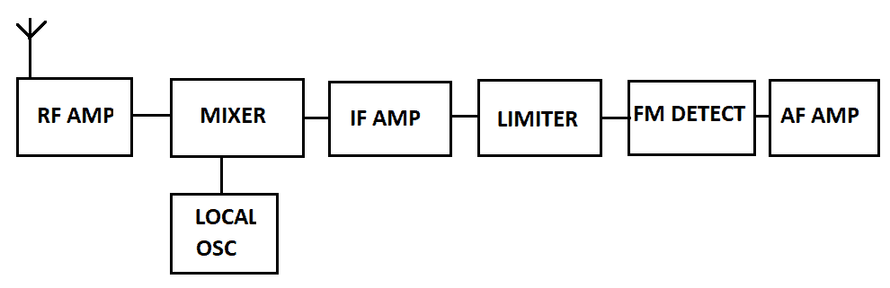
The FM radio signal is picked up by the antenna, which as we discussed in a previous article on FM transmitters, is best as a quarter wavelength.
The RF amp is a VHF amplifier tuned to the FM band and provides rejection to other frequencies and the intermediate frequency image (more on this below).
Then follows the mixer, which mixes the incoming frequency with another frequency from the local oscillator. This is the tuning part, and the result is the creation of two new frequencies—the incoming signal with and without the local oscillator (LO) frequency.
One of these is the needed intermediate frequency (IF). The IF is then sent to an FM detector, which converts frequency to voltage and extracts the audio modulation. This signal is then amplified by the AF amplifier.
Regenerative receivers work differently from the typical FM receiver circuits we just discussed. They were very popular with early radio experimenters since the advent of radio in the ’30s, but because they required a bit of skill and experimentation, they fell out of fashion. Nevertheless, they can and do work very well, and this article will make use of one.
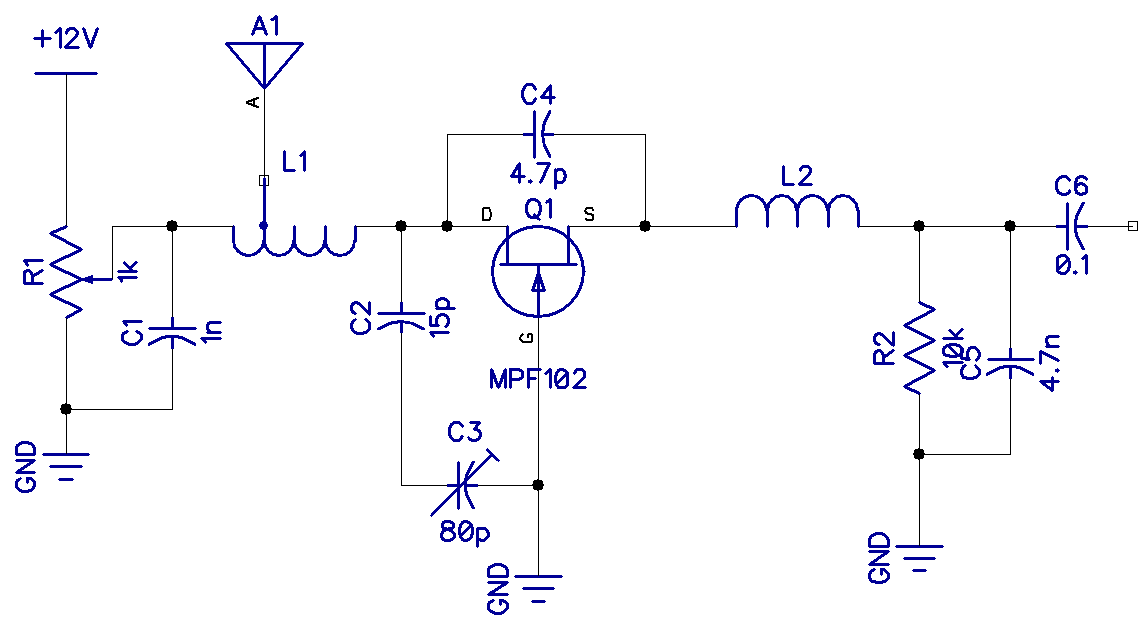
An FM Regenerative Receiver that Works

Shown above is a regenerative FM receiver with just a single JFET transistor (MPF102).
Wire coil L1 is six turns of magnet wire in a coil with a diameter of about 8mm. The tap for the antenna is two turns from the potentiometer end. Wire coil L2 is a choke, which was made by wrapping about 30 turns of magnet wire on an 8mm former.
Potentiometer R1 is the regeneration control, and you adjust it to just before the point of a squealing oscillation.
Variable capacitor C3 is the tuning control.
Capacitor C2 makes the actual capacitance smaller as it is in series to resonate with L1. Actually, the resonance is not so easy to define with a simple formula as it involves the antenna’s inductance and self-capacitance.
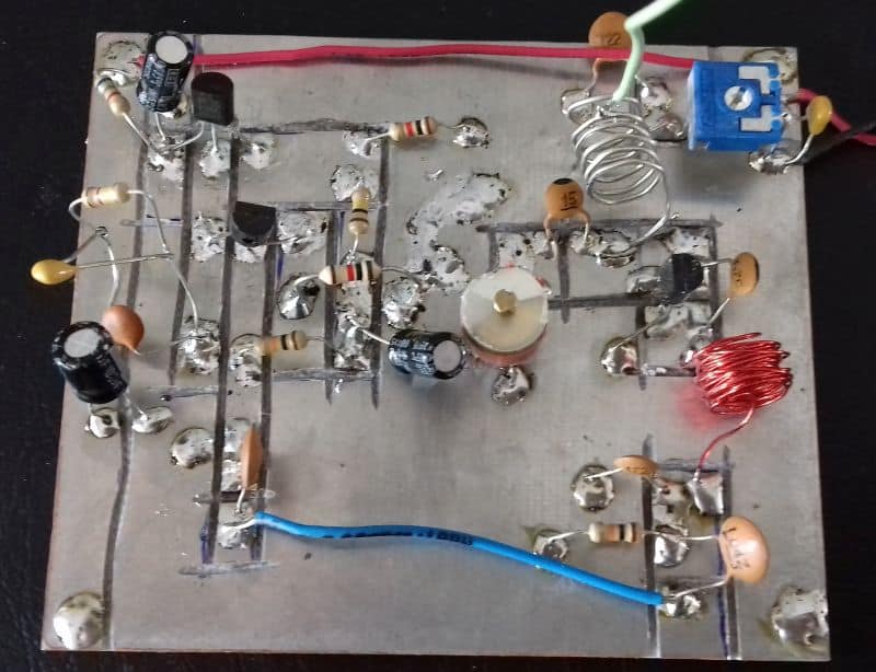
Shown below is my prototype board layout. The receiver is on the right, and as you can see, I added a small two-stage audio pre-amplifier on the left to make it a bit louder:
We have looked at how FM receivers work and presented a fairly simple working design. Personally, I was amazed by how well it worked, considering the actual receiver had only one transistor.
Check out this article to learn how to build an AM radio receiver: How to Build an AM Radio Receiver.
If you have any questions about this project, feel free to leave a comment below.


Hmmmm. Just tried to leave a comment using Brave as my browser, and the reCAPTCHA does not show up properly, so when I did a “Post Comment,” I threw a 404 and the comment was lost. I’m now typing this using Microsoft Edge.
Your last link (to the inventor’s article) is missing an “f” off of the end (it ends with “pd” rather than “pdf”), so it too throws a 404.
Okay, so now that I know that works, next comment:
Good little post of yours. I must admit to being somewhat frustrated understanding FM; there’s a wealth of material on how AM works that’s well-done, both on the Web and in print, but FM seems to have gaps in its explanation. I wonder if it’s possible to break down the similarities and differences between the simplest AM radio (a crystal receiver, I would think) and its simplest FM counterpart. I’ve even seen a site on the Web where the experimenter created an *FM crystal radio*, although the accompanying explanatory text was a tad light on clarity, or indeed, any discussion of how it was possible.
Are the physical parameters (diameter, number of turns) dependent on the frequency range that you have chosen above and if so, what equations did you use to determine these parameters for the receiver?