This is part one in a three part “Ultimate Guide to Op-Amps”. In this article we will learn how op-amps work and how to build circuits with them. There are two other two articles in this series, so be sure to check them out after this one:

- Ultimate Guide to Op-Amps – Part 2: Linear applications
- Ultimate Guide to Op-Amps – Part 3: Non-linear applications
The name op-amp, or operational amplifier, was coined in early uses to do analog mathematics such as integration and differentiation. The first op-amps were vacuum tube types. Early IC op-amps were the µA709 and the LM101, but these evolved into other op-amps quickly due to their enormous usefulness and popularity.
One of the most famous of these was the LM741 op-amp. You still see many circuits using this op-amp. Fortunately, manufacturers kept the pin layouts the same for the ever-increasing and improving range of op-amps.
Because the external feedback components largely determine the behavior of op-amp circuits, you can generally substitute other op-amps. Unless it is a critical application such as ultra-high-frequency response or very low noise or offset.
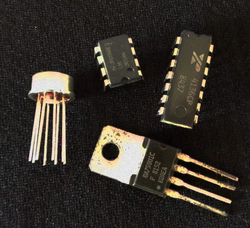
Shown above are some of the packages op amps are available in. A single IC chip may have one, two, or four separate op amps.
How Op Amps Work
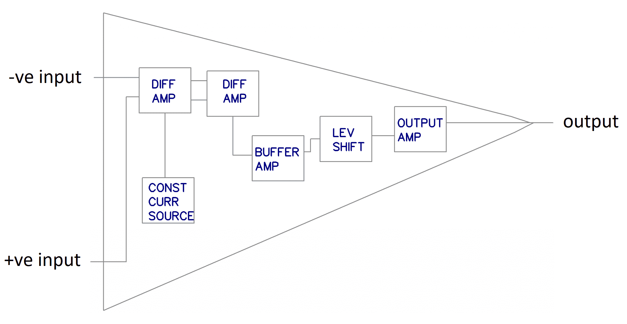
Shown below is an internal block diagram for a simple op-amp (without the power supply).
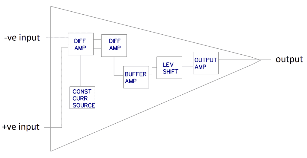
There are two input pins and one output pin. The –ve input is called the inverting input and the +ve input is called the non-inverting input. The inputs are connected to a differential amplifier, followed by more differential amplification stages.
In the differential amplifier, we find what is called a long-tailed pair. Transistors Q1 and Q2 are a pair of very closely matched FETs or bipolar transistors. They are connected to –ve via transistor Q3 which is configured as a constant current source.
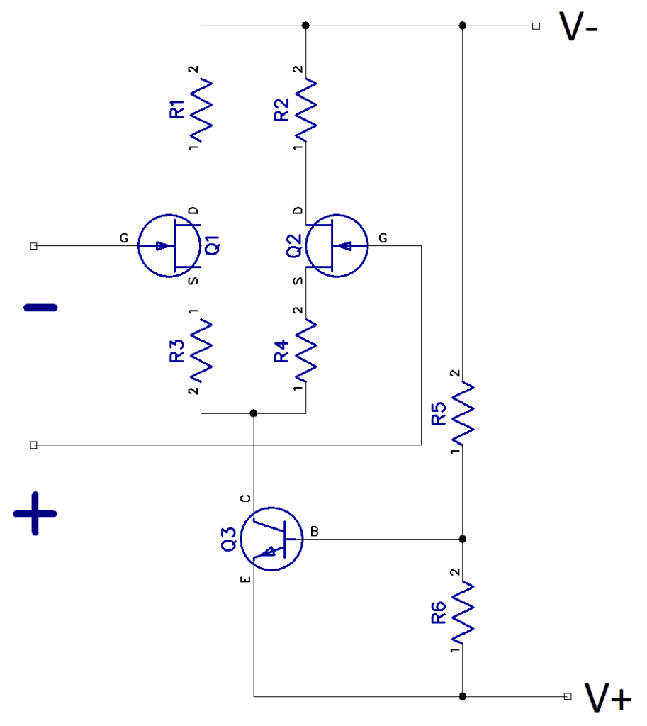
Any difference in voltage between the +ve and -ve inputs will result in a proportional swing in the collectors or drains of Q1 and Q2. This is called the open-loop gain of the op-amp. Any difference in the raw gains of Q1 and Q2 will result in a large unwanted output swing. This can all be brought under our control and made predictable by adding a few components to provide negative feedback between the input and output.
After differential amplification, a level shifting stage centers the voltage swings of output around 0V as all the stages are DC coupled. Finally, a low impedance output amplifier drives the load and prevents any changes on the output from affecting the inputs.
Example Project
Shown below is a circuit for an inverting amplifier with a gain of 100, using the LM741 Operational Amplifier. In an inverting amplifier, the signal at the output is 180 degrees out of phase with the input.
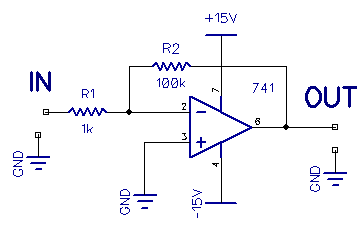
The power supply is shown as +15V and -15V, but the op-amp will work down to quite small supplies, e.g., +/- 9V, limiting the output swing.
If we were to remove resistor R2 in the circuit above, we would have no feedback. This is called an open loop, and the gain would now be a function of the op-amp’s max gain, which is 100dB. But the gain starts to fall off rapidly when the frequency of the input increases:
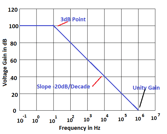
At 10Hz, the gain starts to fall off rapidly at 20dB per decade.
Replacing R2, we now have negative feedback. Unfortunately, this reduces the gain:
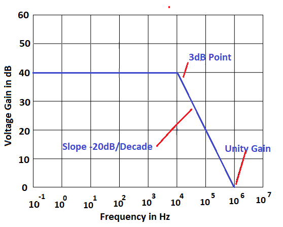
Note where it starts to roll off now—about 37kHz. This would be okay for audio purposes. If we wanted to push it a bit further, we would have to increase the feedback and reduce the gain. If the gain gets too low, we might have to add a second stage of amplification.
Important Op-Amp Specifications
Total harmonic distortion (THD): Noise generated by the op-amp itself. Usually expressed in dB.
Offset voltage: The DC voltage that, when applied between the input pins, will cause a DC output voltage of zero. If both inputs were grounded, the output voltage of the op-amp would not be zero.
Slew rate: The time taken for the output to change for a given input. Specified as V/mS.
Equivalent input noise voltage: The noise performance of the op-amp. An ideal voltage source is placed in series with the input pins that represent the internally generated noise.
Common mode rejection ratio: The ability of the op-amp to reject signals appearing on both inputs at the same time. Particularly important for differential amplifier applications.
Hopefully this article has helped you to understand how op amps work, how to choose one, and how to build a circuit with an op-amp. In the next article, we look at practical examples of some linear circuit applications. Here’s the next article in the series: Ultimate Guide to Op-Amps – Part 2: Linear applications.

Hi,
In the circuit diagram showing the transistors Q1, Q2 and Q3, the power pins V- and V seem to have been inverted.
Looks like you are correct. Graham seems to do this occasionally.