
Have you ever wondered how your smart device changes the screen’s orientation based on the way you are holding your device? The answer lies in a simple device called an accelerometer.

In this tutorial, we will learn how accelerometers work. We will focus specifically on the LIS3DH triple axis accelerometer from Adafruit. We will also learn how to connect this accelerometer to the Raspberry Pi and how to program it with Python.
Here are some real-world applications using an accelerometer with a Raspberry Pi:
- Vibration monitoring
- Tilt detection
- Tap detection
- Free-fall detection
- Screen orientation detection
- Can be used to measure dynamic speed and distance
How Accelerometers Work
An accelerometer is a micro-electromechanical device that measures static or dynamic acceleration forces acting on a device. These forces may be caused by the constant acceleration of gravity, or by acceleration caused by a change in motion or direction.
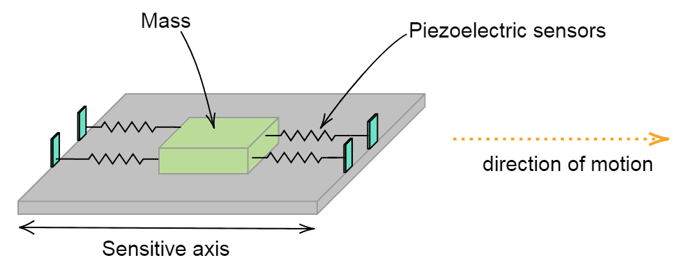
Visualize a mass resting on a movable platform, as shown in the diagram above. As the platform moves in the direction of motion, the mass will want to resist that change in motion. This means that the mass will squeeze a pair of piezoelectric sensors, consequently producing an electric current proportional to the force applied. From this relationship, it becomes easy to calculate the force, and since the mass is a constant, we can determine the acceleration from Force = Mass * Acceleration.
This is the same concept that the LIS3DH accelerometer uses to measure the acceleration along the x, y, and z axes. However, the only difference lies in the transducer. The transducer in the LIS3DH is capacitive instead of piezoelectric.
The LIS3DH Accelerometer
If you look closely at an LIS3DH accelerometer breakout board, you will notice these arrows:
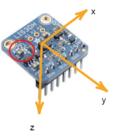
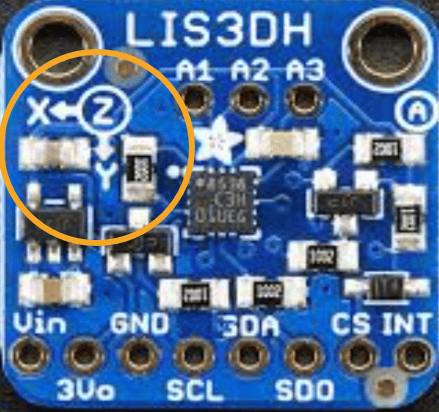
These arrows show us the direction of the acceleration. According to the image on the left above, the acceleration along the x-axis acts in the direction of the x arrow. The same applies to the y-axis. The z-axis takes on a different sign (circle) because the force of gravity acts into the board.
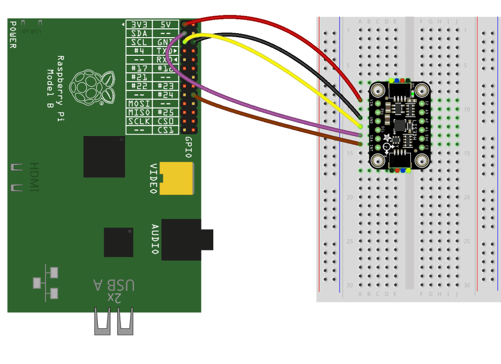
How to Connect the LIS3DH Accelerometer to the Raspberry Pi
As you can see from the pins in the image above, there are two ways of connecting the LIS3DH accelerometer to the Raspberry Pi – I2C or SPI. For this tutorial, I am going to show you both.
We are going to need the following:
Wiring Diagram for SPI Connection
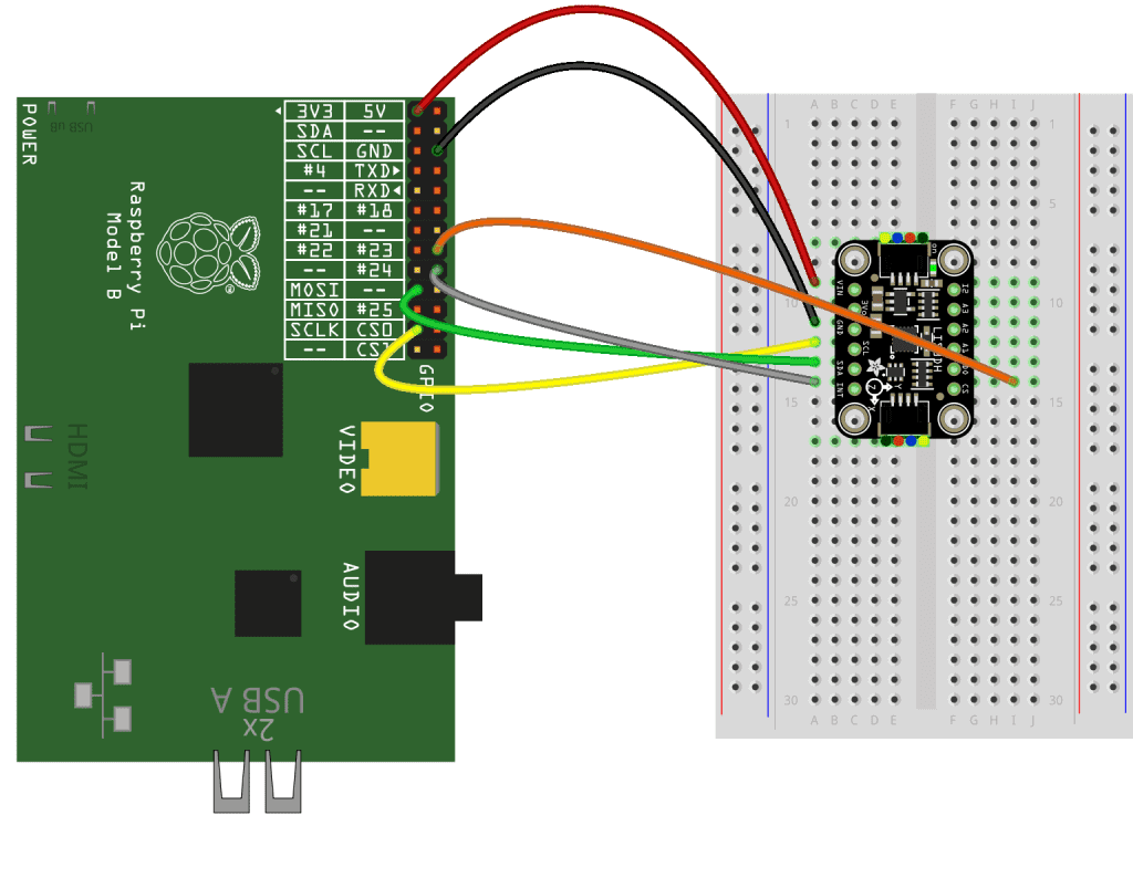
Wiring Diagram for I2C Connection
How to Program the LIS3DH Accelerometer With Python
To communicate with the LIS3DH accelerometer, we will use Adafruit’s circuitPython library. To install this library, run this pip command in the Raspberry Pi terminal:
sudo pip3 install adafruit-circuitpython-lis3dhWith the library installed, you can begin writing a Python script as we have done before.
In the program below, we will read the acceleration values from the LIS3DH accelerometer and display them on the terminal. Copy this code to a text editor on the Raspberry Pi and save it as a file with a “.py” extension:
import time
import board
import digitalio
import busio
import adafruit_lis3dh

i2c = busio.I2C(board.SCL, board.SDA)                # Remove this line if using SPI
int1 = digitalio.DigitalInOut(board.D24)             # Remove this line if using SPI
lis3dh = adafruit_lis3dh.LIS3DH_I2C(i2c, int1=int1)  # Remove this line if using SPI

# spi = busio.SPI(board.SCK, board.MOSI, board.MISO)        # Uncomment this line if using SPI
# cs = digitalio.DigitalInOut(board.D23)                    # Uncomment this line if using SPI
# int1 = digitalio.DigitalInOut(board.D24)                  # Uncomment this line if using SPI
# lis3dh = adafruit_lis3dh.LIS3DH_SPI(spi, cs, int1=int1)   # Uncomment this line if using SPI

x, y, z = lis3dh.acceleration

while True:
  print("%0.3f %0.3f %0.3f" % (x, y, z))
  time.sleep(2)
Code Description
import time, board, digitalio, busio, adafruit_lis3dh: Imports the necessary libraries.i2c = busio.I2C(board.SCL, board.SDA): Initializes the I2C interface.int1 = digitalio.DigitalInOut(board.D24): Sets up an interrupt on Raspberry Pi GPIO 24.x, y, z = lis3dh.acceleration: Queries the LIS3DH for accelerometer values.print("%0.3f %0.3f %0.3f" % (x, y, z)): Prints the values with 3 decimal places.
Running the code above with the command sudo python3 will give us the following output:
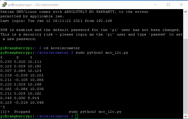
These are the raw values output by the accelerometer’s x, y, and z axes.
Thanks for reading! Hope this tutorial has helped you set up an accelerometer on the Raspberry Pi. Feel free to leave a comment below if you have questions about anything!


