Electronic engineers use a variety of different circuit simulation tools to study the behavior of electronic circuits. But in this tutorial, we will go step-by-step through the process of performing a circuit simulation using National Instrument’s Multisim SPICE simulation software.

Introduction to Multisim
Multisim is a robust circuit design and simulation tool that uses SPICE to simulate analog and digital circuits. In Multisim, you will find circuit analysis tools such as a built-in oscilloscope, logic analyzer, multimeter, function generator, and frequency counter.
Besides performing circuit simulations, you can design circuits, PCBs, and do everything else you can do in a conventional EDA/ECAD tool.
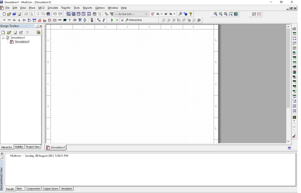
The Multisim user interface consists of several toolbars, a design toolbox, and a workspace window. The main toolbar contains buttons for common functions, while the instruments toolbar contains buttons to add components to the editor window.
How to Use Multisim
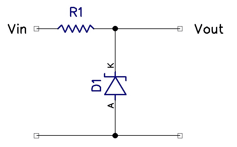
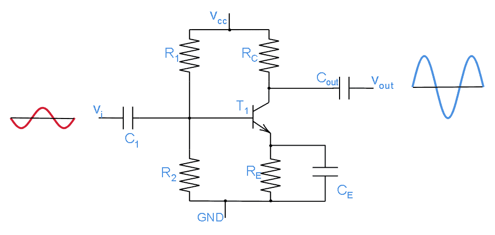
To demonstrate how to use Multisim, we will simulate a circuit for a BJT common emitter amplifier. Here is a schematic of the circuit:
To get started with a circuit simulation, launch Multisim and open a circuit window in the workspace.
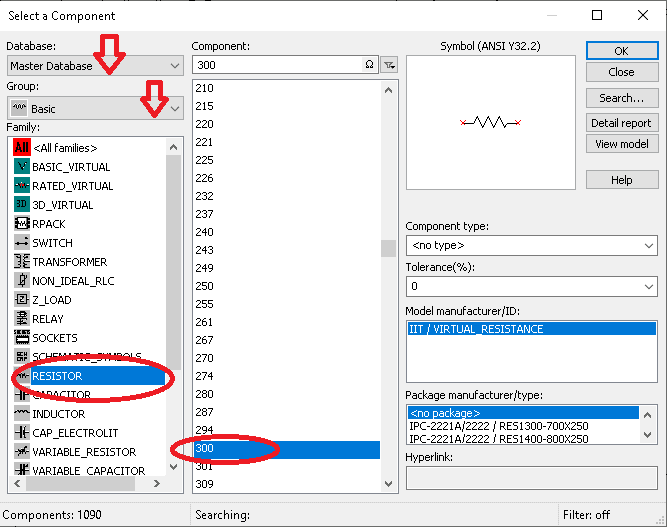
Select “Place” in the toolbar, then click on “Component”. This will take you to the “Select a Component” dialog box.
Make sure to select the “Master Database.”
Under Group, select “Basic” and then the RESISTOR component family. This will display all the resistors in that family.
Next, select the resistor value you want from the list and click “OK.”
We need five resistors for the amplifier circuit above, so we need to place four different resistors. To place capacitors in the workspace, repeat the steps above, but select the CAPACITOR family instead.
For power, select the Sources group and choose the SIGNAL_VOLTAGE_SOURCES family. Select AC_VOLTAGE and click OK.
Finally, under the Sources group, select the POWER_SOURCES family and choose VCC and GROUND.
That’s it! We are now ready to wire up our circuit.
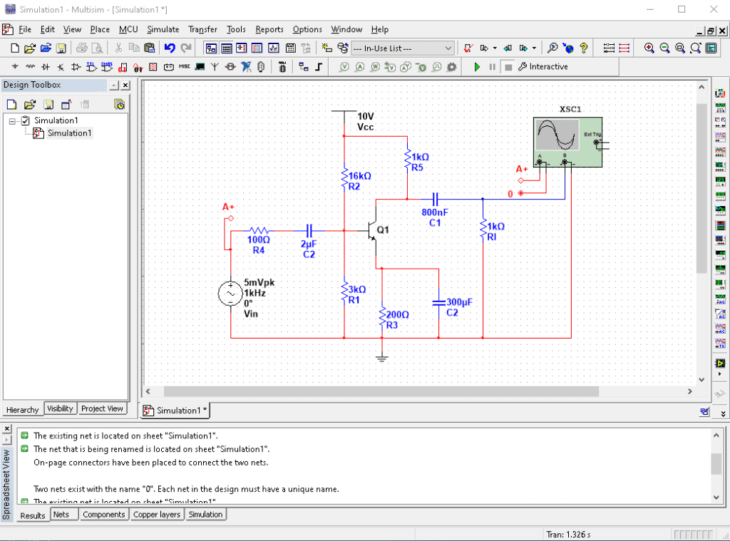
With all of the components for the circuit added to the workspace, we can now connect everything. To connect components in Multisim, click a pin and drag the wire to the pin you want to connect to:
Run the Circuit Simulation
This is what we have been waiting for. Now we can simulate the circuit and view the results on a virtual oscilloscope.
To set up the tools we will use to analyze this circuit, click “Simulate” on the toolbar and then select “Instruments.” On the list that appears, choose “Oscilloscope” and place it anywhere in the design window.
Now we will connect the circuit’s input to channel A of the oscilloscope and connect the output to channel B, as shown in the image above. Finally, click the “Run” button to begin the simulation.
If everything has been set up correctly, you should get the following message:
—— Checking SPICE netlist for Simulation1 – Wednesday, 11 August 2021, 3:09:41 PM ——
======= SPICE Netlist check completed, 0 error(s), 0 warning(s) =======
Viewing the Results
To view the results from the circuit simulation, double click on the oscilloscope and you will see the following waveform diagram:
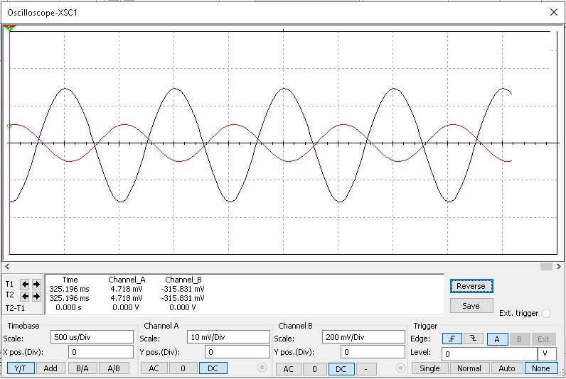
You can adjust the voltage and time base of the oscilloscope until your waveform is visible in the window.
Congratulations! You have completed a straightforward circuit simulation using an oscilloscope in Multisim. There are lots of other ways to analyze the output of simulated circuits in Multisim. Check out their website to learn more, and be sure to leave a comment below if you have questions about anything!