Sometimes, it is impractical to use a single Arduino to read from a sensor and show the result at that location. For example, it might be in an unreachable or dangerous location, or where running a cable out is not practical. In such instances, we need to transmit the sampled data to a second remote Arduino, such as a nearby control room.

For this tutorial, we are going to use a BMP280 barometric pressure and temperature sensor connected to one Arduino and then use a 2.4GHz radio link provided by two NRF24L01 digital transceivers to relay this data to a second Arduino some distance away. This distance should be less than about 50m depending on the walls in between. Transceiver means a combined transmitter and receiver in one unit.
Here, we are going to have one Arduino fitted with a BMP280 connected via I2C, and the NRF24L01 connected with SPI. This will transmit a radio signal to a second Arduino, also fitted with a second NRF24L01 running as a receiver which will display the incoming data on the serial monitor. You can use an LCD display as well. The NRF24L01 can work in both directions. For example, the receiver could reply with an acknowledgment but that will add more complexity than we need for this demo.
Something to bear in mind, this is a true SHF (Super High Frequency) radio link, and like all such radio links, the higher the better. Plus, it tends to ‘behave’ like a defused light beam, so the fewer obstructions the better.
How the BMP280 Works
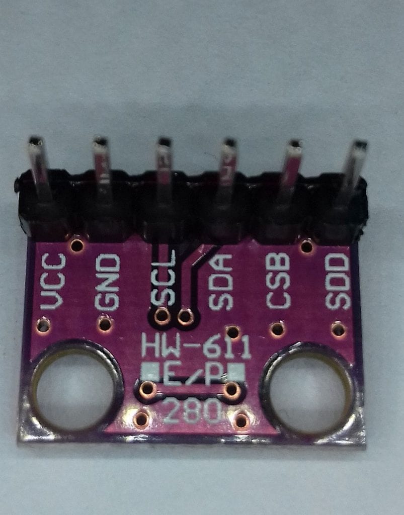
The BMP280 comes in different types depending on where you buy it. Be aware because some are 5V devices and some are 3.3V devices. Also, some are SPI or I2C and some are not. This article will use the I2C 3.3V version. This one, although 3V, is 5V-compliant on the data pins. We are using an I2C version as the NRF24L01 is using the SPI bus.
The pressure range is 300hPa to 1100hPa, which is about 10m below sea level to 9km high. Between 950hPa and 1050hPa, the altitude accuracy is +/-1m which is pretty awesome.
On some units, the I2C address is 0x77 and on others, it is 0x76. There is a useful address scanner in the Arduino playground here. If it does not find the address, check your wiring.
| BMP280 | Uno |
| VCC | 3.3V |
| GND | GND |
| SCL | A5 |
| SDA | A4 |
| CSB | Not used |
| SDD | Not used |
How the NRF24L01 Works
The NRF24L01 is an SPI-connected digital transceiver, capable of transmitting and receiving data in the 2.4GHz ISM band (ISM stands for Industrial, Scientific & Medical). This is the same band used by Bluetooth and WiFi and does not require a license as it is low-power. It is a 3V powered unit, but the data lines are 5V compliant so no conversion is required. You can drive its VCC pin straight from the UNO’s 3.3V pin. The SPI interface runs up to 10mbps. Each module is operated on the same frequency or channel between 2.400 and 2.525 GHz. Within each channel, there are 6 ‘pipes’ allowing up to 6 links in each channel. This means one master could be listening to 6 slaves, all on the same channel but on different ‘pipes’.
| NRF24L01 | Uno |
| VCC | 3.3V |
| GND | GND |
| MOSI | 11 |
| MISO | 12 |
| SCK | 13 |
| CE | 9 |
| CSN | 8 |
| IRQ | Not used |
How to Connect the NRF24L01 to the Arduino
These are the parts you will need to build the example project below:
- 2 x Arduino Uno
- 2 x NRF24L01 transceiver module
- 1 x BMP280 barometric pressure sensor
- Breadboard
- Jumper wires
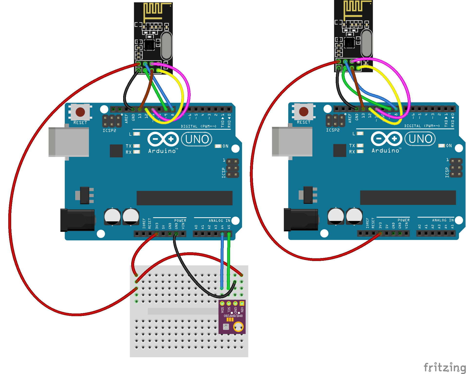
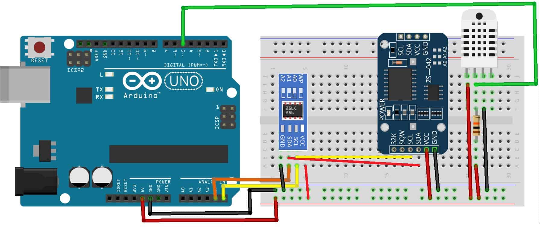
Once you have the parts, connect everything together following this wiring diagram:

If you want to learn more about the Arduino, check out our Ultimate Guide to the Arduino video course. You’ll learn basic to advanced Arduino programming and circuit building techniques that will prepare you to build any project.
Installing the Libraries
There are a few libraries required:
- #include <SPI.h>
- #include <nRF24L01.h>
- #include <RF24.h>
- #include <Adafruit_BMP280.h>
- SPI.h is a standard library
- The BMP280 library can be found here
- Both NRF libraries can be found here
Notes on the Program
- The
sizeof()function detects the length of the variable in bytes, i.e. an int is 2 bytes long, float 4 bytes etc. - You MUST have a matching data type on the receiving side because what the NRF24 actually sends is a series of bytes that is
sizeof()long. - If you try to stuff 2 bytes into 1 byte at the receiving end, you will get garbage.
- If you use an array, you can send several pieces of data in one message provided that the 32-byte limit is not exceeded. You can send any type of data i.e. char strings, integers or floats. Just be sure to have the receiver expecting to catch the same data type. In our example, because we want 3 decimal values, we use an array of 3 floats. The max length of a single message is 32 bytes. So 3 floats need 12 bytes, leaving plenty of headroom.
- All the pins except CE and CSN have to be wired as given. However, these two can be any convenient pins and declared as:
RF24 nrf(9, 8); // CE, CSN
Arduino Code for the Master
//nrf2401 transmitter:
#include <SPI.h>
#include <nRF24L01.h>
#include <RF24.h>
#include <Adafruit_BMP280.h>
RF24 nrf(9, 8);  // CE, CSN
Adafruit_BMP280 bmp;

const byte linkAddress[6] = "link1";
float QNH = 1022.67; //Change the "1022.67" to your current sea level barrometric pressure (https://www.wunderground.com)
const int BMP_address = 0x76;

float pressure;
float temperature;
float altimeter;
float data[3];
char charVal[17];
////////////////////////////////////////////////////
void setup()
{
  Serial.begin(9600);
  Serial.println("BMP280/NRF24L01 link");
  nrf.begin();
  bmp.begin(BMP_address);
  nrf.openWritingPipe(linkAddress);  //set the address
  //nrf.setPALevel(RF24_PA_LOW);   //keep tx level low to stop psu noise, can remove this but then put in decoupling caps
  // Options are: RF24_PA_MIN=-18dBm, RF24_PA_LOW=-12dBm,  RF24_PA_HIGH=0dBm.
  nrf.setPALevel(RF24_PA_HIGH);
  nrf.stopListening();  //act as a transmitter
}
///////////////////////////////////////////////////
void loop()
{
 pressure = bmp.readPressure()/100;  //and conv Pa to hPa
 temperature = bmp.readTemperature();
 altimeter = bmp.readAltitude (QNH); //QNH is local sea lev pressure

 data[0] = pressure;
 data[1] = temperature;
 data[2] = altimeter;
 //----- display on local monitor: ------------
 Serial.print(data[0]); Serial.print("hPa  ");
 Serial.print(data[1]);
 Serial.write(0xC2);  //send degree symbol
 Serial.write(0xB0);  //send degree symbol
 Serial.print("C   ");
 Serial.print(data[2]); Serial.println("m");
 //---------------------------------------------

  nrf.write(data, sizeof(data)); //spit out the data array

  delay(300);
}
/////////////////////////////////////////////////
Notes on the Master Code:
float QNH = 1022.67; QNH is an aviation term. It is a correction factor that when applied to an altimeter, will allow it to accurately read the elevation above sea level at the current location. This varies from day to day and even hour to hour. Pilots need to set this every time they fly to calibrate their altimeters. If pilots are unable to get this, for example, while flying over the ocean, they all use 1013, then their altimeters all read using the same reference. This lets them fly at spaced heights to avoid a collision. It can be obtained from weather websites.
For example, here in Cape Town: https://tides4fishing.com/af/south-africa/cape-town/forecast/atmospheric-pressure
You don’t have to do this. But without a corrected value of the altitude reading at your location, it will be incorrect (as you have to take local variations in atmospheric pressure into consideration) and might even display negative. The actual pressure and temperature are still correct.
nrf.openWritingPipe(linkAddress); starts one of the 125 channels. The transmitter and receiver must have the same address.
nrf.setPALevel(RF24_PA_HIGH); sets the power level of the transmitter. HIGH might cause instability issues if your 3.3V power is via long wires. Best to put in a 100uF capacitor across it, but LOW might be better for longer battery life.
nrf.stopListening(); tells the module to behave as a transmitter and conversely, nrf.startListening(); tells it to behave as a receiver.
The data to be transmitted is printed locally on the serial monitor (if connected) as well as being sent out to the receiver. The lines Serial.write(0xC2); Serial.write(0xB0); send a degree symbol to the serial monitor (this may be different for some PC’s).
If you are using an LCD you can do this with: lcd.print((char) 223); //add deg sign.
Lastly, nrf.write(data, sizeof(data)); transmits the contents of the data array. Note that it needs to know how many bytes to send and sizeof() gets that.
Arduino Code for the Slave
 //nrf2401 receiver
#include <SPI.h>
#include <nRF24L01.h>
#include <RF24.h>

RF24 nrf(9, 8);  // CE, CSN
const byte linkAddress[6] = "link1";  //address through which two modules communicate.
const byte greenLED = 10;
float data[3];
/////////////////////////////////////////////////////////////////////
void setup()
{
  Serial.begin(9600);
  Serial.println("Starting");
  pinMode(greenLED, OUTPUT);

  nrf.begin();
  nrf.openReadingPipe(0, linkAddress);  //set the address
  nrf.startListening();   //Set nrf as receiver
}
///////////////////////////////////////////////////
void loop()
{
   digitalWrite(greenLED, HIGH);
   delay(50);
   digitalWrite(greenLED, LOW);
   delay(50);

   if (nrf.available())  //Read the data if available in buffer
     {
      nrf.read(&data, sizeof(data));
     Serial.print(data[0]); Serial.print("hPa  ");
     Serial.print(data[1]);
     Serial.write(0xC2);  //send degree symbol
     Serial.write(0xB0);  //send degree symbol
     Serial.print("C   ");
     Serial.print(data[2]); Serial.println("m");
     }
}
//////////////////////////////////////////////
Notes on Slave Code:
Most of the code is pretty similar to the master, but nrf.openReadingPipe(0, linkAddress); starts one of the 6 pipes. The transmitter and receiver must have the same address. Note that there is an additional parameter here that sets which reading pipe is being used (0 in this case).
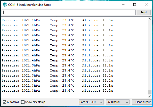
NRF24L01 Serial Window
If all is wired correctly, the serial window on the receiving Arduino should show the following:
Be sure to leave a comment below if you have any questions or have trouble setting this up.


2.4-2.5 ghz not 25 ghz
Any idea how to time stamp and log this data to a sd card or file? Plot it? Any simple anwswers probably not. Also on this project listed here, what is the distance these can communicate effectively? (If anyone knows)
Hi Rich,
We actually just posted a tutorial on how to log Arduino data to an SD card… Check it out here: https://www.circuitbasics.com/writing-data-to-files-on-an-sd-card-on-arduino/
This is a terrific sketch. No more need for Strings.
I don’t own a BMP280 so I used 4 individual sensors instead.
data[0] = light;
data[1] = servo;
data[2] = temp;
data[3] = freq;
float data[4];
All 4 sensor readings display perfectly on an OLED.
Thanks a million.
John
How to add a program for error detection and error correction on this project “ 2.4 GHZ WIRELESS COMMUNICATION BETWEEN TWO ARDUINOS”
If it’s possible please do assist with the program code.
Nrf is unable to receive data can anyone guide me
Thank you very much for the detailed information.
Very good project.
However, I could not get it to work until I added 22mF capacitors to the 3.3v supply on the NRF modules. This is suggested by various people using the NRF24L01 modules to smooth out the power supply.
Anyway now working well with a Dallas Temp sensor.