Remember when printers, mice, and modems had thick cables with those huge clunky connectors? The ones that literally had to be screwed into your computer? Those devices were probably using UARTs to communicate with your computer. While USB has almost completely replaced those old cables and connectors, UARTs are definitely not a thing of the past. You’ll find UARTs being used in many DIY electronics projects to connect GPS modules, Bluetooth modules, and RFID card reader modules to your Raspberry Pi, Arduino, or other microcontrollers.

UART stands for Universal Asynchronous Receiver/Transmitter. It’s not a communication protocol like SPI and I2C, but a physical circuit in a microcontroller, or a stand-alone IC. A UART’s main purpose is to transmit and receive serial data.
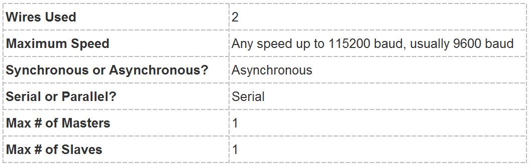
One of the best things about UART is that it only uses two wires to transmit data between devices. The principles behind UART are easy to understand, but if you haven’t read part one of this series, Basics of the SPI Communication Protocol, that might be a good place to start.
Introduction to UART Communication
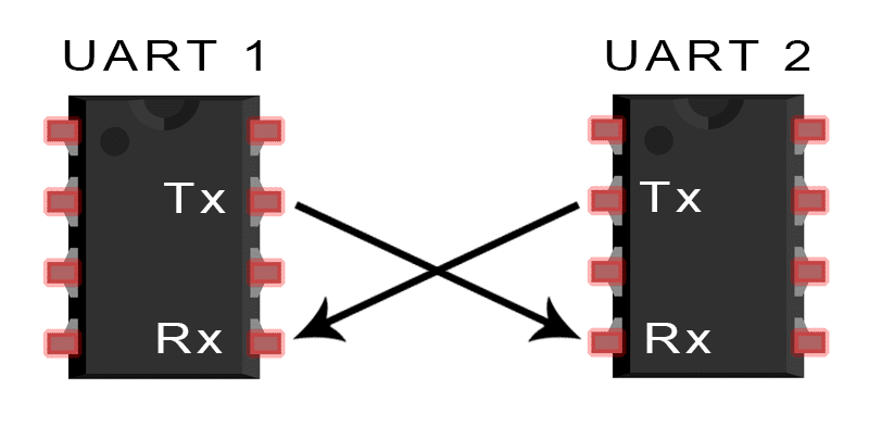
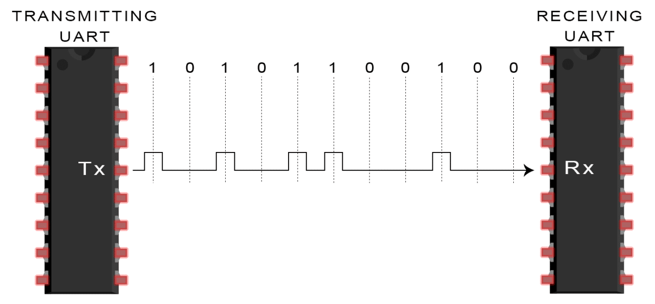
In UART communication, two UARTs communicate directly with each other. The transmitting UART converts parallel data from a controlling device like a CPU into serial form, transmits it in serial to the receiving UART, which then converts the serial data back into parallel data for the receiving device. Only two wires are needed to transmit data between two UARTs. Data flows from the Tx pin of the transmitting UART to the Rx pin of the receiving UART:
UARTs transmit data asynchronously, which means there is no clock signal to synchronize the output of bits from the transmitting UART to the sampling of bits by the receiving UART. Instead of a clock signal, the transmitting UART adds start and stop bits to the data packet being transferred. These bits define the beginning and end of the data packet so the receiving UART knows when to start reading the bits.
When the receiving UART detects a start bit, it starts to read the incoming bits at a specific frequency known as the baud rate. Baud rate is a measure of the speed of data transfer, expressed in bits per second (bps). Both UARTs must operate at about the same baud rate. The baud rate between the transmitting and receiving UARTs can only differ by about 10% before the timing of bits gets too far off.
Both UARTs must also must be configured to transmit and receive the same data packet structure.
How UART Works
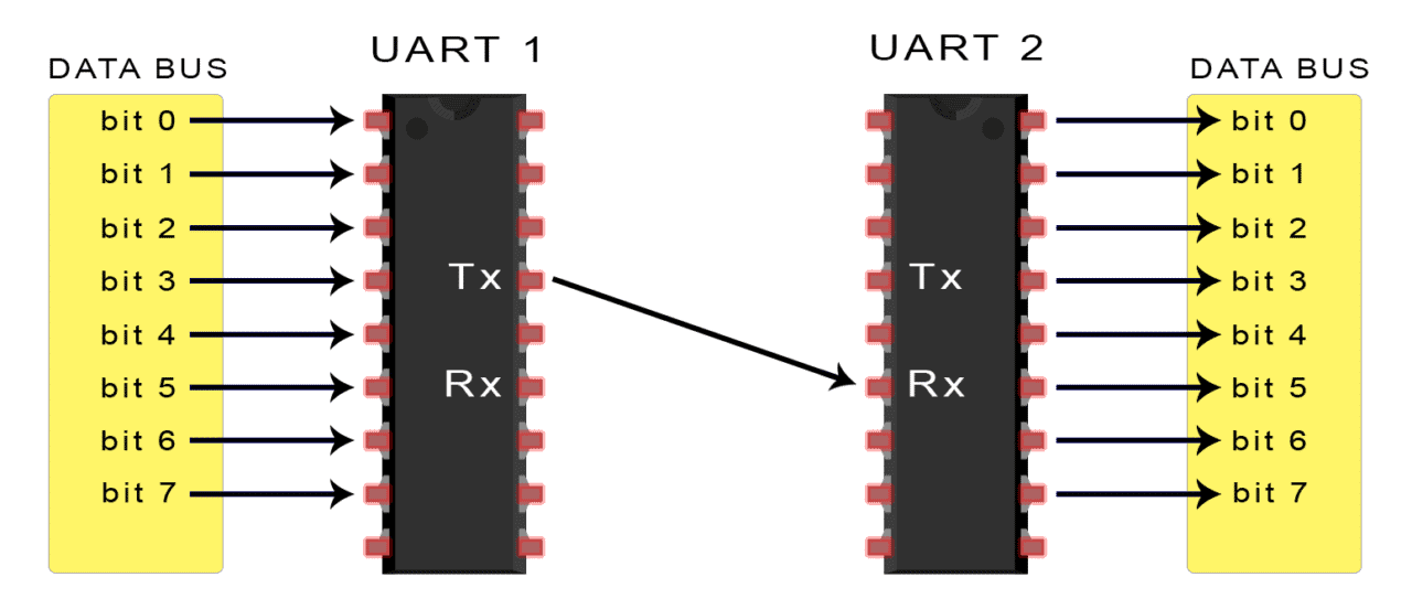
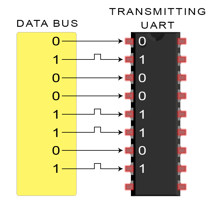
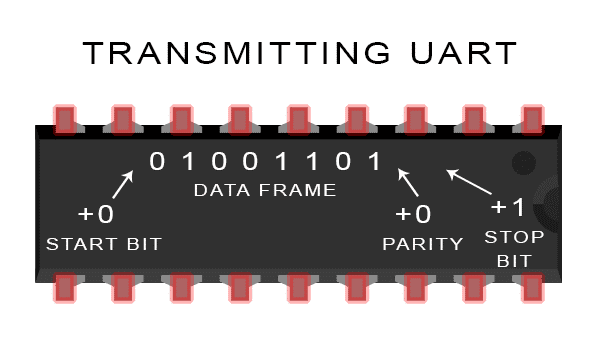
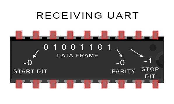
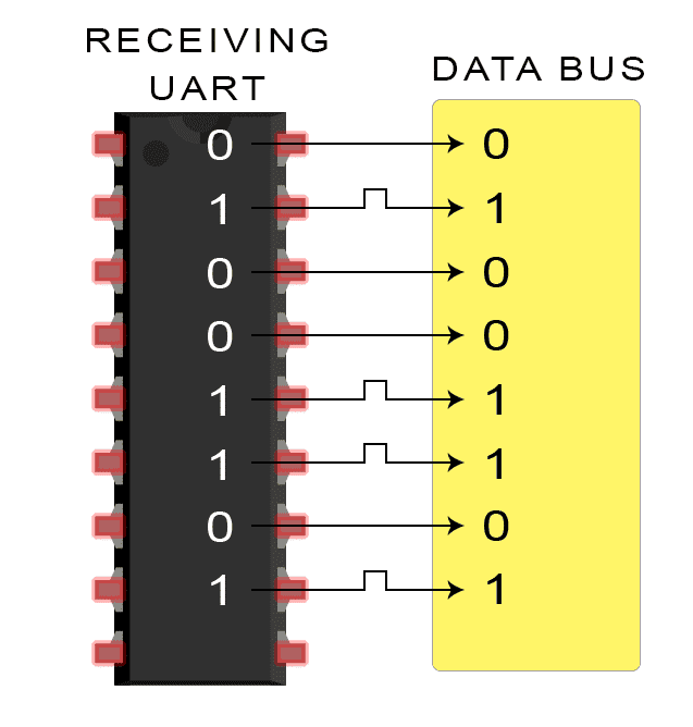
The UART that is going to transmit data receives the data from a data bus. The data bus is used to send data to the UART by another device like a CPU, memory, or microcontroller. Data is transferred from the data bus to the transmitting UART in parallel form. After the transmitting UART gets the parallel data from the data bus, it adds a start bit, a parity bit, and a stop bit, creating the data packet. Next, the data packet is output serially, bit by bit at the Tx pin. The receiving UART reads the data packet bit by bit at its Rx pin. The receiving UART then converts the data back into parallel form and removes the start bit, parity bit, and stop bits. Finally, the receiving UART transfers the data packet in parallel to the data bus on the receiving end:
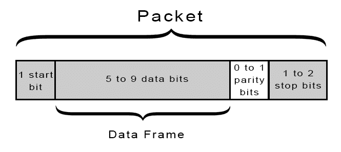
UART transmitted data is organized into packets. Each packet contains 1 start bit, 5 to 9 data bits (depending on the UART), an optional parity bit, and 1 or 2 stop bits:
Start Bit
The UART data transmission line is normally held at a high voltage level when it’s not transmitting data. To start the transfer of data, the transmitting UART pulls the transmission line from high to low for one clock cycle. When the receiving UART detects the high to low voltage transition, it begins reading the bits in the data frame at the frequency of the baud rate.
Data Frame
The data frame contains the actual data being transferred. It can be 5 bits up to 8 bits long if a parity bit is used. If no parity bit is used, the data frame can be 9 bits long. In most cases, the data is sent with the least significant bit first.
Parity
Parity describes the evenness or oddness of a number. The parity bit is a way for the receiving UART to tell if any data has changed during transmission. Bits can be changed by electromagnetic radiation, mismatched baud rates, or long distance data transfers. After the receiving UART reads the data frame, it counts the number of bits with a value of 1 and checks if the total is an even or odd number. If the parity bit is a 0 (even parity), the 1 bits in the data frame should total to an even number. If the parity bit is a 1 (odd parity), the 1 bits in the data frame should total to an odd number. When the parity bit matches the data, the UART knows that the transmission was free of errors. But if the parity bit is a 0, and the total is odd; or the parity bit is a 1, and the total is even, the UART knows that bits in the data frame have changed.
Stop Bits
To signal the end of the data packet, the sending UART drives the data transmission line from a low voltage to a high voltage for at least two bit durations.
Steps of UART Transmission
1. The transmitting UART receives data in parallel from the data bus:
2. The transmitting UART adds the start bit, parity bit, and the stop bit(s) to the data frame:
3. The entire packet is sent serially from the transmitting UART to the receiving UART. The receiving UART samples the data line at the pre-configured baud rate:
4. The receiving UART discards the start bit, parity bit, and stop bit from the data frame:
5. The receiving UART converts the serial data back into parallel and transfers it to the data bus on the receiving end:
Advantages and Disadvantages of UARTs
No communication protocol is perfect, but UARTs are pretty good at what they do. Here are some pros and cons to help you decide whether or not they fit the needs of your project:
Advantages
- Only uses two wires
- No clock signal is necessary
- Has a parity bit to allow for error checking
- The structure of the data packet can be changed as long as both sides are set up for it
- Well documented and widely used method
Disadvantages
- The size of the data frame is limited to a maximum of 9 bits
- Doesn’t support multiple slave or multiple master systems
- The baud rates of each UART must be within 10% of each other
Continue on to part three of this series, Basics of the I2C Communication Protocol to learn about another way electronic devices communicate. Or if you haven’t already, check out part one, Basics of the SPI Communication Protocol.
And as always, let us know in the comments if you have questions or anything else to add! If you liked this article and want to see more like it, be sure to subscribe- we send out an email when ever we publish new posts.


Nice one. But there is a scope of introducing RS232 concept here
Thank you for this beautiful explanation.. Great
You say in 2 places it only uses 2 wires. If you want tx and rx you need a ground wire as well. ie It must use 3 wires not 2
right you need a ground wire
As follow up articles yes to both- RS232 &RS485.
But so often than not we consider UART to be a protocol. And consider RS232 and UART as the same thing.
In that aspect, not mentioning the protocols here is good decision.
Its Beautifully Explained. Frankly Speaking, After a hell lot of search over Internet and books, THis is the only Place where I literally Understood what Exactly UART is and its working.
Thanks a Lot guys.
A request: can you write another article to Explain How Exactly an IC (made of transistors) Adds these bits (Start,parity,stop) and Removes them. I mean how exactly they do this intelligent stuff at Electronics level ? Please explain its Circuit basics. :)
Well Explained and Nice Article.Thank You :)
It’s a good explanation.
its very good explanation. thnks a lot.
You are welcome Mote Saand
Excellent.
This was helpful but I’m unsure about one thing. If two bits gets flipped in error, wouldn’t the total still match with the parity bit? Or more generally, if an even number of bits get flipped in error, the error won’t be detected. Is that right?
Correct, the receiver will not notice the error, but, pending good design of the hardware, this is going to be a rare case.
Your analysis is correct. That is why parity checking is rudimentary and may not prevent all errors. But the odds of two bits being changed is much higher than just one so this method works in most cases of low level hardware communication.
Nice work. As a begginer this helps me a lot .can you do this for uart with interrupts also
Well explanation
well explanation,and its easy to understand
friendly explanation ,,nice
thanx
really easy of understanding and way of explanation is good
Nice one!
very good expaination. I have one question that we also use Usb micro port for connectiing uart hardware and the other USB port type A to our laptop. How does it work? does uart support USB ports also?
no uart does not support the usb ports
“It’s not a communication protocol like SPI and I2C, but a physical circuit in a microcontroller, or as a separate IC”.
This part confuses me. I understand that UART is a physical hardware IC, but it must also be a protocol because how else would there be communication? The bits can’t just be sent randomly. Data is sent through packets just like you described in a timely matter and specific order. Isn’t that in essence a protocol? Thanks.
It is a very confusing statement, because I2C and SPI perform a similar low level task – transmitting and receiving bytes between devices.
A UART doesnt have to be a physical IC, and it doesnt even need to be circuitry inside a microcontroller – just like I2C and SPI it can be implemented entirely in software by “bit banging” general purpose I/O pins.
good explanation to thanks
thanks for the good information. simple and best.
i’m not understanding of parity bit
Parity bit is that it show that how many bit are there and if there are even number is there then it will pass bit 1 or bit 0
Good post. Its in a language everyone can understand. But i also want to know how communication (data transfer) between data bus and UART occurs.
It is really a very good explanation as i m not from electrical background.
Can anyone say how can I transmit 1000 bytes of data through uart protocol
Awsome explenation really
Really good explaination. Now i understood very clearly what exactly The UART performs internally
i am working on UART so any body can send VHDL CODE to my mail thoshifkhan1992@gmail.com
It is an nice explanation .Thank you
1) The two UARTs communicating having the same baud rate, does that mean the clocks of both the UARTs are synchronized ( i.e clock cycle starts and stops at the same time) ?
I didnt get from where that allowed difference of 10% came from. Can you please explain!!!
10% come fromm start and stop bits and parity too
Thank you soo much.. Thanks a ton. Really U ppl had done a great job. Now seriously I understood the working principle, data transmission of bits and everything without any doubt. Thanks again and again. Hope you upload more and more sessions and concepts like this.
The clocks of the two systems do not need to be synchronised in any way, and they can run at entirely different speeds.
UART is self-timed – each individual bit occupies a specific amount of time based on the configured baud rate, e.g. ~104uS at 9600 baud (1 / 9600). So the key to making this work, using 9600 baud as an example, is that the transmitter needs to alternate the TX pin at 104uS intervals, and the receiver needs to sample its RX pin at 104uS intervals to reconstruct what has been sent. The receiver starts this process once it sees the start bit.
If the transmitter or receiver differ significantly enough in this measurement because they have such different baud rates configured, then the rate at which the transmitter alternates its TX pin and the rate that the receiver samples its RX pin means you either miss entire bits, or read the same bit more than once.
10% of error is way too much and is a bad suggestion. See: https://www.allaboutcircuits.com/technical-articles/the-uart-baud-rate-clock-how-accurate-does-it-need-to-be/
So its not possible to communicate between two mcu’s with different clock speeds?
Why we using 9bits institute data transmission
After a long days after completing engineering understood the concept of UART
Thanks for sharing.
Nice one…where can/is this UART protocol applied. Which module uses this protocol
Good one.
why we use ground in the uart communication as a common terminal to both transmitter and receiver.
You need that third wire (GND) for electrical purposes. Both devices have to agree on a voltage reference. Otherwise, the meaning of 1s and 0s would be lost.
A fantastic explanation ever about UART!
Nice explanation! Suggestion to add: if two bits change during the transmission of the datapacket then the Parity bit error check doesn’t work. So it’s a rather weak form of error checking.
Thanks for the feedback, I am going to improve the UART technology pretty soon, stay tuned for updates!
Great explanation. if the baud rate is 9600 bits per second, this means that every 1/9600 second am sending a bit, this raises the following question, the time between sending two consecutive bits, what’s happening in this time? the serial line getting back to zero, right?
Wow its a great article. Can u guyz just upload the ‘C codes’ happening inside the transmission and receiving.
That will be great!!!
I love it
Really very good explanation, pls keep going posting on updates
That was just awesome.I was totally new to the world of electronics and I don’t even know what the UART is?Now I got to know in just a single reference of yours that what a UART is and how it works.This helped me a lot in my final project…MY BIG BIG Thanks to you.
Yeah! Really nice explanation in an easy manner
Good Explanation…
Great explanation with simple words. Anyone even without a prior knowledge of communication protocols can learn the concept perfectly with the help of this article. Thank you!
Why we are connecting common ground in UART..
Please cover this point also..
Good Explanation
https://www.drurylandetheatre.com/
what will happen if RX uart is in off state and TX uart is started transmission(both are physically connected).
how TXuart will come to know whether RX uart received or not.
‘If the parity bit is a 1 (odd parity), the 1 bits in the data frame should total to an odd number.”
This line is under the parity paragraph.
I think the 1 bits in the data frame should total to an even number because data frame includes data of size 5-8(data frame) where the next bit is a parity. For odd parity(parity bit as 1) the sum of 1 bits has to be even in the data frame.
NICE EXPLANATION BRIEFLY ………
GIVE SUGGESTIONS GET ORIGINAL DATA SHEET OF UART ……
ld include mainly propane mixtures, most commonly propane and butane mixtures. Mixtures contain more propane in winter in the northern hemisphere and more butane in summer.
In the United States,cooking gas cylinder two grades of liquefied petroleum gas are mainly sold: commercial propane and HD-5. Propane/butane mixtures are also listed in these specifications.
Propylene, butene and various other hydrocarbons are also commonly present in small concentrations. HD-5 will limit the propylene content that can be placed in LPG to 5% and be used as an automatic gas specification.
Strong odorant ethanethiol, easy to detect
A powerful odorant, ethanethiol, was added to make leaks easy to detect. The internationally recognized European standard is EN 589. In the United States, Tetrahydrothiophene (thiophene) or amyl mercaptan are also approved, although they are not currently used.
LPG is prepared by refining oil or “wet” natural gas, almost entirely from fossil fuel sources, and is manufac
As you explained above
In parity check when ever the UART Rx will get to know that the data frame had changed, will it send a request for original data frame or what it is going to do after knowing the data frame had changed ??
Best damn explanation yet!
UART is full duplex or half duplex
The UART component can be configured for Full Duplex, Half Duplex, RX only or TX only versions. All versions provide the same basic functionality differing only in the amount of resources utilized
Ref: https://www.cypress.com/file/132486
Can I know why it’s not called a communication protocol still two UART’s have to communicate with Tx and Rx signals as in SPI : MOSI, MISO?
Thank you very much. It is explained very well for beginners.
Very good material. Please upload CAN protocol also.
Thank U
Hello Sir,
As you said due to Electromagnetic Radiation Data bits can change..! and Error can be detected by the Receiver
What if Data bits doesn’t change and the parity bit got change due to radiation..??
how does the receiver distinguish between a data bit and stop bit. In ‘Steps of UART transmission’ step #3, diagram shows that the last bit transmitted is 1 – how can receiver distinguish between this and any other data bit.
Hi,
May I know the Use of Rx Pin of UART Transmitter and Tx Pin of UART Receiver while the Data Transmission is happening from Tx Pin of UART Transmitter to Rx Pin of UART Receiver
Thank you for the clear explanation.
Looking forward to more such articles.
I have a Project with 5 LX-16A Bus Servos.
I have LewanSoul Bus Servo Controller
I need to setup a Coordinated Action
I need to set the servo motors to swing 180 degrees
ID 1 will start and return to 0 degrees.
ID 2 will start 5 to 10 seconds after ID 1
ID 3 will start 5 to 10 seconds after ID 2
ID 4 will start 5 to 10 seconds after ID 3
ID 5 will start 5 to 10 seconds after ID 4.
I have No knowledge of electronic communication.
Your UART explanation has opened a new window.
Can you help setting these Data Packets for the Coordinated Action.
Alternatively direct me to someone that can help me with this project.
Thank you
Cassim
E:gurupeer@gmail.com
Hi Cassim This was not my article?
I see it did not say who wrote it?
Ill try find out
“If the parity bit is a 0 (even parity), the 1 bits in the data frame should total to an even number. If the parity bit is a 1 (odd parity), the 1 bits in the data frame should total to an odd number.”
This is a little bit misleading and poorly written. Parity bit is not 0 on even parity and 1 in odd parity. Parity bit can be 1 or 0 depending on the situation. In case of even parity, the total number of ‘1’ bits, including the parity bit, should be even. In contrast, in odd parity, the total number of ‘1’ bits, including parity bit, should be odd. So parity bit is either ‘1’ or ‘0’ to satisfy the requirement I described before. An example always makes things more clear.
Consider transmission of byte ‘10100010’. The number of ‘1’ bits is 3 (odd).
– Even parity: to make the number of ‘1’ bits even we need one more (3+1 = 4 which is even). Consequently the parity bit should be ‘1’, resulting in transmission of ‘101000101’
– Odd parity: the number of ‘1’ bits is already odd so we don’t need to add something. Consequently the parity bit should be ‘0’, resulting in transmission of ‘101000100’
Hope that makes it more clear.
Uart, no longer just an acronym. From what I gathered from this awesome write up and using memory of other articles. My thought is the uart, is a shift register with rx\tx on one side and bus inputs filled by mcu, cpu, whatever.laptop uart Tx h, Rx h, chilling. Bus filled (tx L for 1 baud) = start. 5-9 high or lows (1=5v 1baud) (0=0v 1baud} (5-8 if use parity) parity bit (count 1s in 5-8 bits compair to me the parity bit which is not added due to the fact I’m set by the mcu, cpu, or whatever.) Once all my bits are in and the stop bit brings my rx high for 2 or more baud all bits transfer to bus instantly on there own pin, wire whatever, and bam ready for another start bit. Only about 9588 baud left in this second so whatever
Hi, i’ve much enjoyed these basic concepts from the series. Thanks a lot! Can you tell me names of nice books on the subjects (SPI, I²C and UART) ?
need explanation on Ethernet communication