An analog-to-digital converter is a device used to convert an analog signal (like the output from a photoresistor or a thermistor) to a binary signal that can be processed by a digital computer or microcontroller.

There are multiple ways to convert an analog signal into a binary digital signal, but in this tutorial we will discuss successive approximation as this is probably the most common way to do it.
Sampling
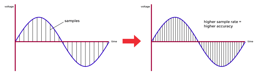
Every AC waveform has a given frequency, wavelength, and amplitude. To convert this wave into a digital signal, we measure the amplitude of the AC waveform at periodic intervals known as the sample rate. A higher sample rate will produce a more accurate representation of the AC waveform:
How Analog to Digital Converters Work
Shown in Figure 1 below is a block diagram of the ADC used in the ATMEGA328.
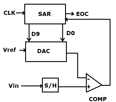
The clock CLK provides the sampling rate, SAR is the successive approximation register, EOC is an output to the processor to indicate the current sample is complete, Vref is either the 5V supply, or an external voltage reference. The DAC is a digital to analog converter, Vin is the analog input pin, S/H is the sample and hold, and COMP is the comparator.
The conversion process is initiated by an analog signal entering the ADC at Vin. Upon receiving the signal, the control unit of the ADC will give a command to the successive approximation register, which starts generating the digital signal by the successive approximation method. The generated digital data is converted to an analog signal by the DAC, and then compared to the current analog signal and the reference voltage. The digital data available at this instant is given as an output through the output register.
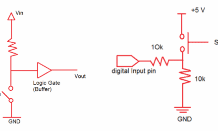
The heart of the ADC is the sample and hold (S/H) shown in Figure 2 below:
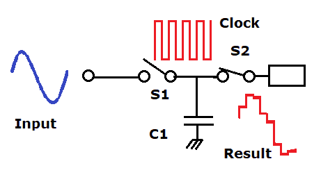
For each sample clock cycle, S1 closes and S2 opens to allow the capacitor to rapidly charge up to the current value of the waveform. S2 then closes while S1 opens, and the voltage is read by the comparator.
How Digital to Analog Conversion Works
How can we relate the digital bits output by an ADC to an analog voltage level? Say one sample from a 10 bit ADC was 0001100100. We first need to convert this binary number into an integer.
How to convert binary numbers into integers. First line up the binary number as shown in the table below, with the numbers of possible combinations increasing from right to left:
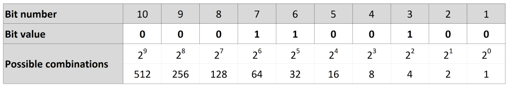
Now, multiply the bit value by the number of possible combinations:
0*512 + 0*256 + 0*128 + 1*64 + 1*32 + 0*16 + 0*8 + 1*4 + 0*2 + 0*1 = 100
So, what voltage did we read?
In an Arduino ADC, the range of ADC outputs is limited to a range between 0 and 1023. Assuming we are using the local 5V as our reference, we have:
(1023 / 5V) * Vin = integer value returned.
So if the ADC outputs an integer value of 100 (as above), the voltage is:
Voltage = (5V * 100) / 1023 = 0.488V
There you have it! Analog to digital converters are rather complex devices, but they are really good to know about. Thanks for reading and be sure to leave a comment below if you have any questions!


