Infrared (IR) communication is a widely used and easy to implement wireless technology that has many useful applications. The most prominent examples in day to day life are TV/video remote controls, motion sensors, and infrared thermometers.

There are plenty of interesting Arduino projects that use IR communication too. With a simple IR transmitter and receiver, you can make remote controlled robots, distance sensors, heart rate monitors, DSLR camera remote controls, TV remote controls, and lots more.
In this tutorial I’ll first explain what infrared is and how it works. Then I’ll show you how to set up an IR receiver and remote on an Arduino. I’ll also show you how to use virtually any IR remote (like the one for your TV) to control things connected to the Arduino.
Watch the video for this tutorial here:
Now let’s get into the details…
What is Infrared?
Infrared radiation is a form of light similar to the light we see all around us. The only difference between IR light and visible light is the frequency and wavelength. Infrared radiation lies outside the range of visible light, so humans can’t see it:
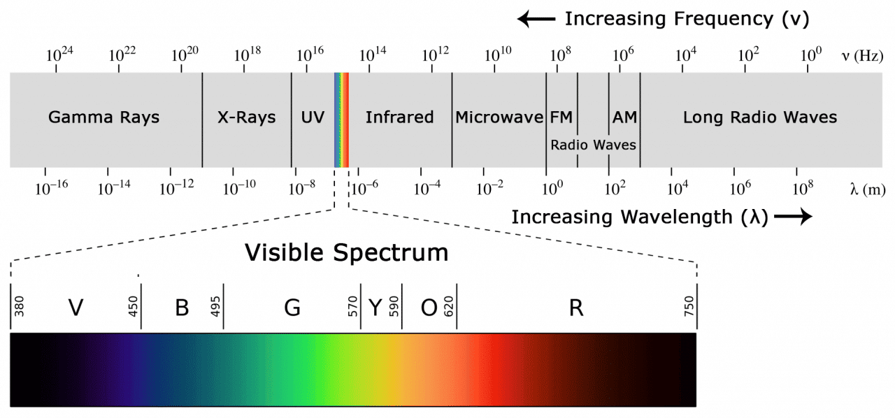
Because IR is a type of light, IR communication requires a direct line of sight from the receiver to the transmitter. It can’t transmit through walls or other materials like WiFi or Bluetooth.
How IR Remotes and Receivers Work
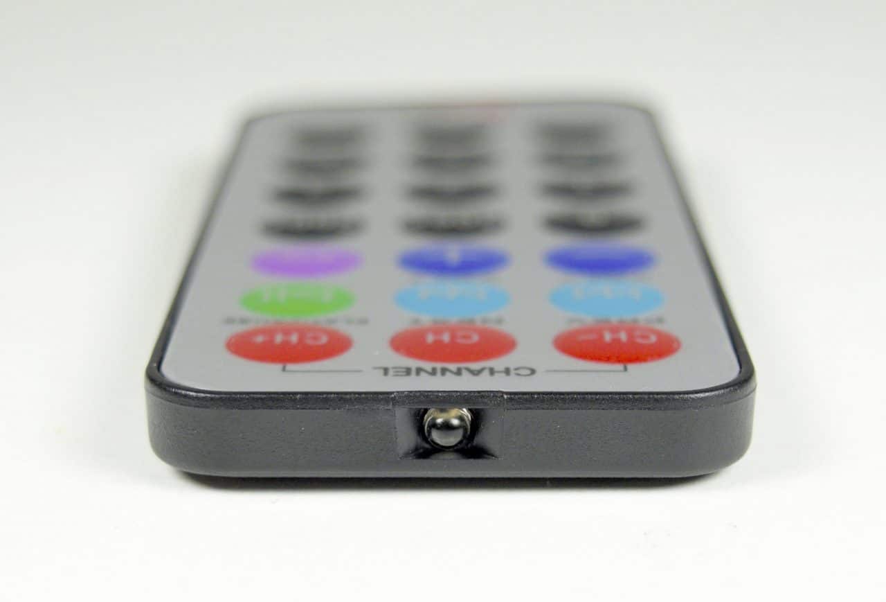
A typical infrared communication system requires an IR transmitter and an IR receiver. The transmitter looks just like a standard LED, except it produces light in the IR spectrum instead of the visible spectrum. If you have a look at the front of a TV remote, you’ll see the IR transmitter LED:
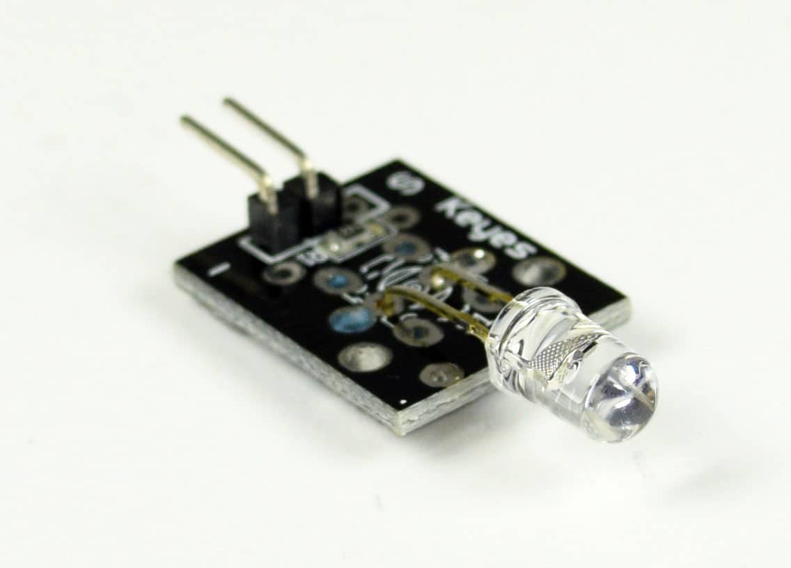
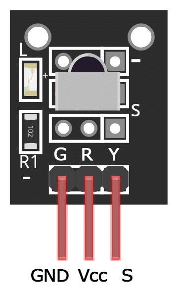
The same type of LED is used in IR transmitter breakout boards for the Arduino. You can see it at the front of this Keyes IR transmitter:
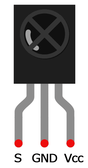
The IR receiver is a photodiode and pre-amplifier that converts the IR light into an electrical signal. IR receiver diodes typically look like this:
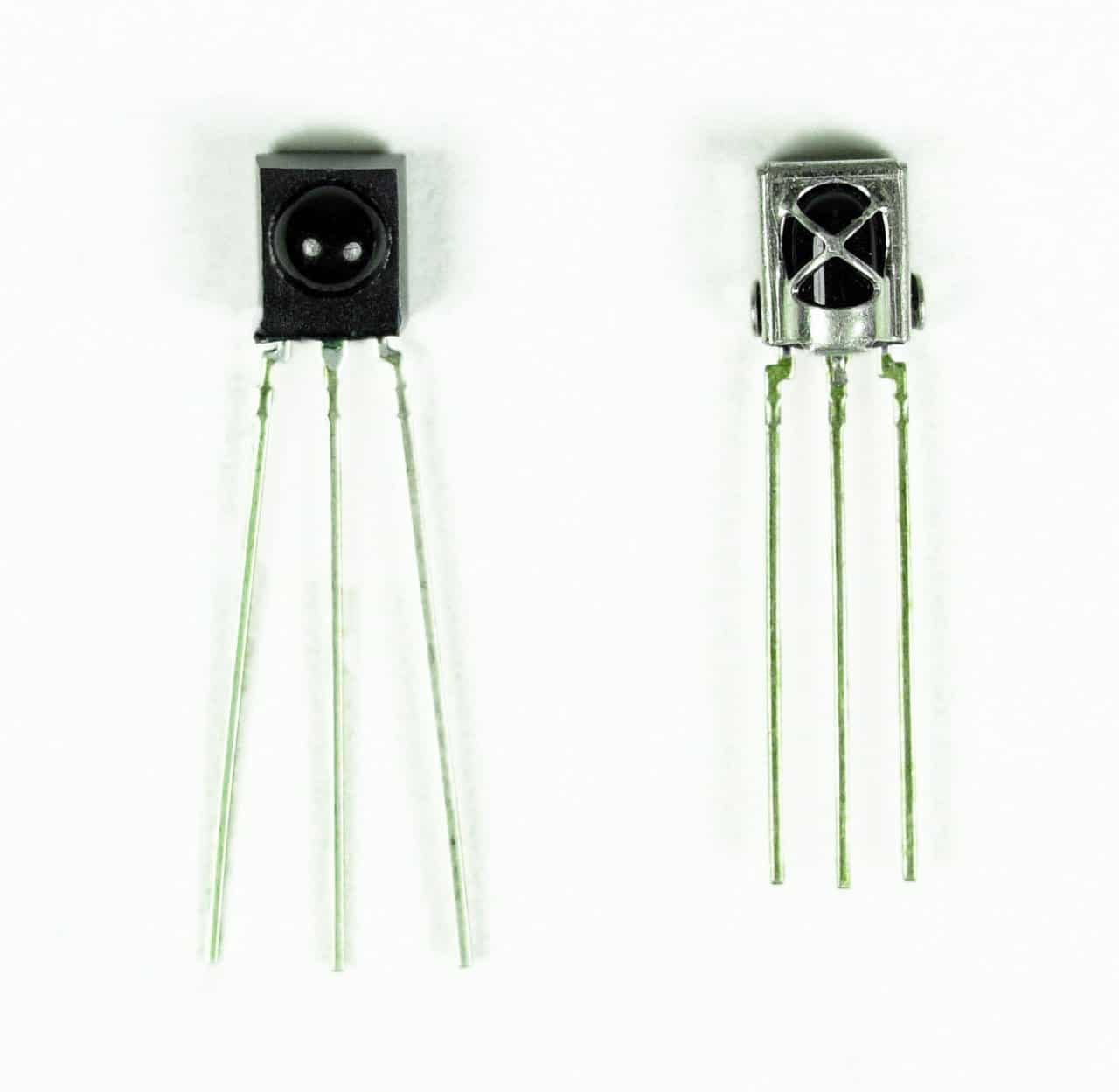
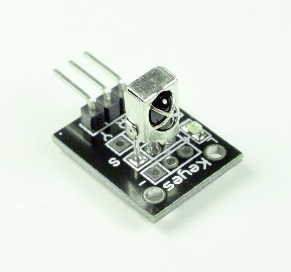
Some may come on a breakout board like this:
IR Signal Modulation
IR light is emitted by the sun, light bulbs, and anything else that produces heat. That means there is a lot of IR light noise all around us. To prevent this noise from interfering with the IR signal, a signal modulation technique is used.
In IR signal modulation, an encoder on the IR remote converts a binary signal into a modulated electrical signal. This electrical signal is sent to the transmitting LED. The transmitting LED converts the modulated electrical signal into a modulated IR light signal. The IR receiver then demodulates the IR light signal and converts it back to binary before passing on the information to a microcontroller:
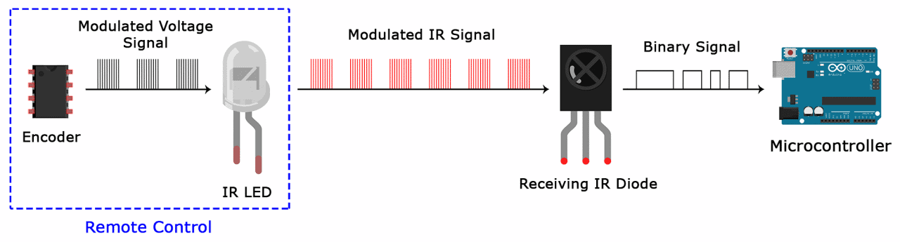
The modulated IR signal is a series of IR light pulses switched on and off at a high frequency known as the carrier frequency. The carrier frequency used by most transmitters is 38 kHz, because it is rare in nature and thus can be distinguished from ambient noise. This way the IR receiver will know that the 38 kHz signal was sent from the transmitter and not picked up from the surrounding environment.
The receiver diode detects all frequencies of IR light, but it has a band-pass filter and only lets through IR at 38 kHz. It then amplifies the modulated signal with a pre-amplifier and converts it to a binary signal before sending it to a microcontroller.
IR Transmission Protocols
The pattern in which the modulated IR signal is converted to binary is defined by a transmission protocol. There are many IR transmission protocols. Sony, Matsushita, NEC, and RC5 are some of the more common protocols.
The NEC protocol is also the most common type in Arduino projects, so I’ll use it as an example to show you how the receiver converts the modulated IR signal to a binary one.
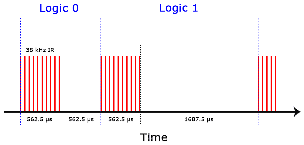
Logical ‘1’ starts with a 562.5 µs long HIGH pulse of 38 kHz IR followed by a 1,687.5 µs long LOW pulse. Logical ‘0’ is transmitted with a 562.5 µs long HIGH pulse followed by a 562.5 µs long LOW pulse:
This is how the NEC protocol encodes and decodes the binary data into a modulated signal. Other protocols differ only in the duration of the individual HIGH and LOW pulses.
IR Codes
Each time you press a button on the remote control, a unique hexadecimal code is generated. This is the information that is modulated and sent over IR to the receiver. In order to decipher which key is pressed, the receiving microcontroller needs to know which code corresponds to each key on the remote.
Different remotes send different codes for the keypresses, so you’ll need to determine the code generated for each key on your particular remote. If you can find the datasheet, the IR key codes should be listed. If not though, there is a simple Arduino sketch that will read most of the popular remote controls and print the hexadecimal codes to the serial monitor when you press a key. I’ll show you how to set that up in a minute, but first we need to connect the receiver to the Arduino…
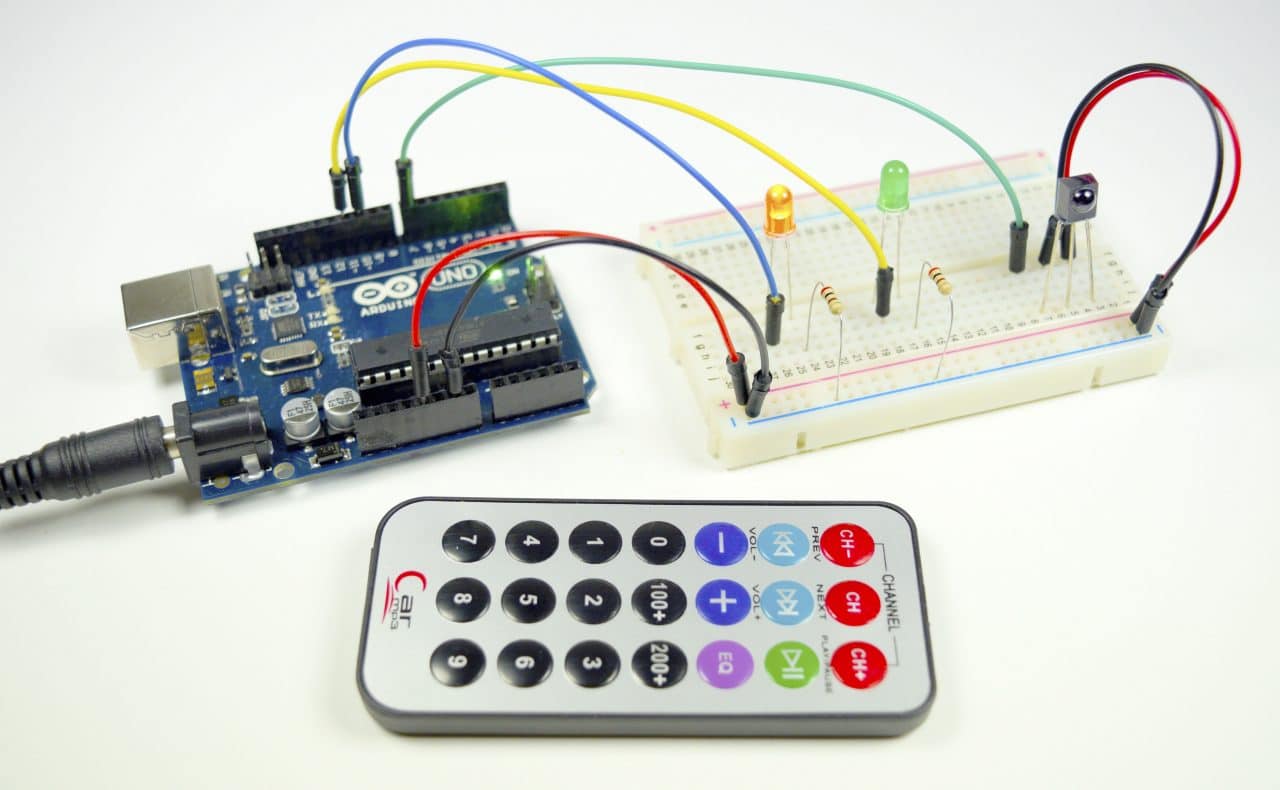
How to Connect an IR Receiver to the Arduino
There are several different types of IR receivers, some are stand-alone, and some are mounted on a breakout board. Check the datasheet for your particular IR receiver since the pins might be arranged differently than the HX1838 IR receiver and remote set I am using here. However, all IR receivers will have three pins: signal, ground, and Vcc.
Lets get started with the hardware connections. The pin layout on most breakout boards looks like this:
The pinout of most stand-alone diodes is like this:
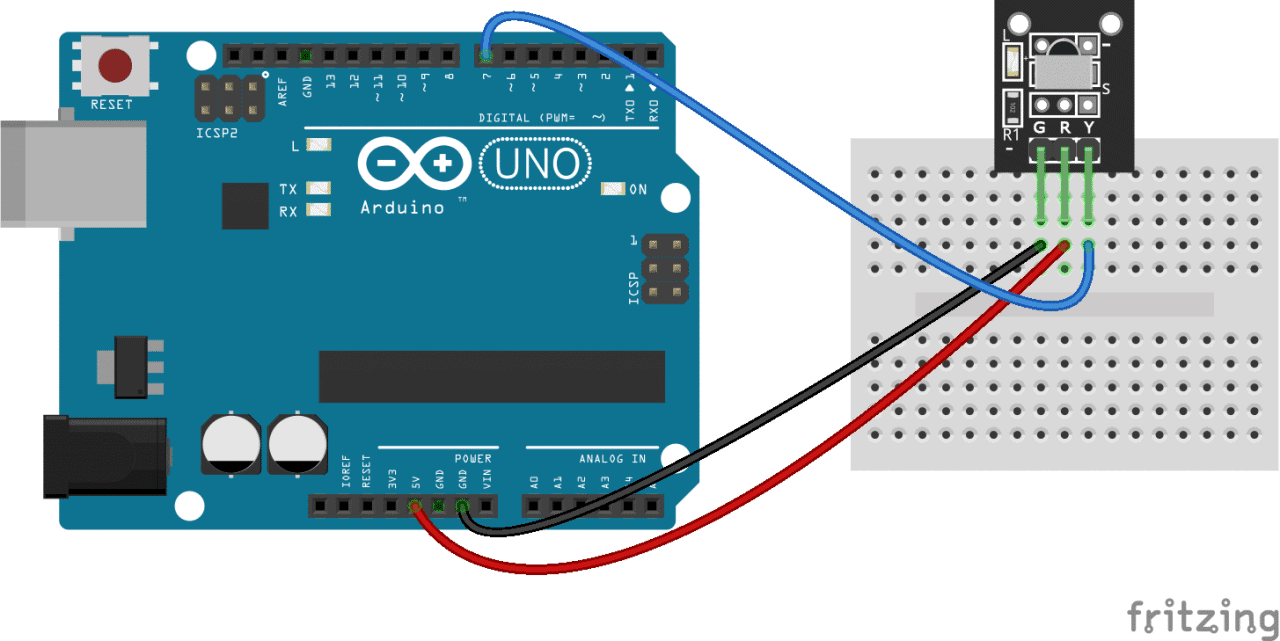
To connect a breakout board mounted IR receiver, hook it up to the Arduino like this:
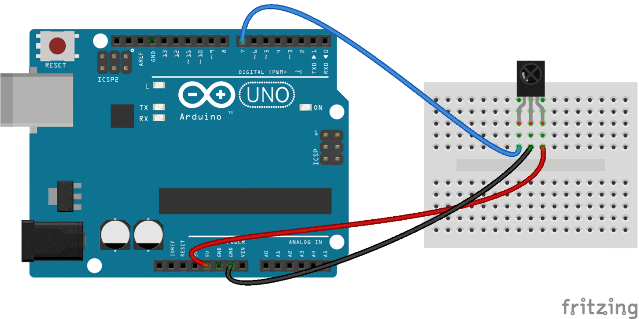
To connect a stand-alone receiver diode, wire it like this:
Programming the IR Receiver
Once you have the receiver connected, we can install the Arduino library and start programming. In the examples below, I’ll show you how to find the codes sent by your remote, how to find the IR protocol used by your remote, how to print key presses to the serial monitor or an LCD, and finally, how to control the Arduino’s output pins with a remote.
Install the IRremote Library
We’ll be using the IRremote library for all of the code examples below. You can download a ZIP file of the library from here.
To install the library from the ZIP file, open up the Arduino IDE, then go to Sketch > Include Library > Add .ZIP Library, then select the IRremote ZIP file that you downloaded from the link above.
Find the Codes for Your Remote
To find the key codes for your remote control, upload this code to your Arduino and open the serial monitor:
#include <IRremote.h>

const int RECV_PIN = 7;
IRrecv irrecv(RECV_PIN);
decode_results results;

void setup(){
  Serial.begin(9600);
  irrecv.enableIRIn();
  irrecv.blink13(true);
}

void loop(){
  if (irrecv.decode(&results)){
        Serial.println(results.value, HEX);
        irrecv.resume();
  }
}
Now press each key on your remote and record the hexadecimal code printed for each key press.
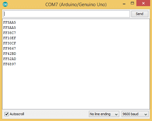
Using the program above, I derived a table of keys and their corresponding codes from the remote that came with my HX1838 IR receiver and remote set. Note that you will receive a 0XFFFFFFFF code when you press a key continuously.
| Key | Code |
| CH- | 0xFFA25D |
| CH | 0xFF629D |
| CH+ | 0xFFE21D |
| << | 0xFF22DD |
| >> | 0xFF02FD |
| >|| | 0xFFC23D |
| – | 0xFFE01F |
| + | 0xFFA857 |
| EQ | 0xFF906F |
| 100+ | 0xFF9867 |
| 200+ | 0xFFB04F |
| 0 | 0XFF6897 |
| 1 | 0xFF30CF |
| 2 | 0xFF18E7 |
| 3 | 0xFF7A85 |
| 4 | 0xFF10EF |
| 5 | 0xFF38C7 |
| 6 | 0xFF5AA5 |
| 7 | 0xFF42BD |
| 8 | 0xFF4AB5 |
| 9 | 0xFF52AD |
Find the Protocol Used by Your Remote
Knowing which protocol your remote uses can be useful if you want to work on some more advanced projects. Or you might just be curious. The program below will identify the protocol used by your remote. It should even work on most of the remote controls around your house.
#include <IRremote.h>

const int RECV_PIN = 7;
IRrecv irrecv(RECV_PIN);
decode_results results;

void setup(){
  Serial.begin(9600);
  irrecv.enableIRIn();
  irrecv.blink13(true);
}

void loop(){
  if (irrecv.decode(&results)){
        Serial.println(results.value, HEX);
        switch (results.decode_type){
            case NEC: Serial.println("NEC"); break ;
            case SONY: Serial.println("SONY"); break ;
            case RC5: Serial.println("RC5"); break ;
            case RC6: Serial.println("RC6"); break ;
            case DISH: Serial.println("DISH"); break ;
            case SHARP: Serial.println("SHARP"); break ;
            case JVC: Serial.println("JVC"); break ;
            case SANYO: Serial.println("SANYO"); break ;
            case MITSUBISHI: Serial.println("MITSUBISHI"); break ;
            case SAMSUNG: Serial.println("SAMSUNG"); break ;
            case LG: Serial.println("LG"); break ;
            case WHYNTER: Serial.println("WHYNTER"); break ;
            case AIWA_RC_T501: Serial.println("AIWA_RC_T501"); break ;
            case PANASONIC: Serial.println("PANASONIC"); break ;
            case DENON: Serial.println("DENON"); break ;
          default:
            case UNKNOWN: Serial.println("UNKNOWN"); break ;
          }
        irrecv.resume();
 }
}
Print Keys to the Serial Monitor
I extended the code above to print the key value instead of the hexadecimal code:
#include <IRremote.h>

const int RECV_PIN = 7;
IRrecv irrecv(RECV_PIN);
decode_results results;
unsigned long key_value = 0;

void setup(){
  Serial.begin(9600);
  irrecv.enableIRIn();
  irrecv.blink13(true);
}

void loop(){
  if (irrecv.decode(&results)){

        if (results.value == 0XFFFFFFFF)
          results.value = key_value;

        switch(results.value){
          case 0xFFA25D:
          Serial.println("CH-");
          break;
          case 0xFF629D:
          Serial.println("CH");
          break;
          case 0xFFE21D:
          Serial.println("CH+");
          break;
          case 0xFF22DD:
          Serial.println("|<<");
          break;
          case 0xFF02FD:
          Serial.println(">>|");
          break ;
          case 0xFFC23D:
          Serial.println(">|");
          break ;
          case 0xFFE01F:
          Serial.println("-");
          break ;
          case 0xFFA857:
          Serial.println("+");
          break ;
          case 0xFF906F:
          Serial.println("EQ");
          break ;
          case 0xFF6897:
          Serial.println("0");
          break ;
          case 0xFF9867:
          Serial.println("100+");
          break ;
          case 0xFFB04F:
          Serial.println("200+");
          break ;
          case 0xFF30CF:
          Serial.println("1");
          break ;
          case 0xFF18E7:
          Serial.println("2");
          break ;
          case 0xFF7A85:
          Serial.println("3");
          break ;
          case 0xFF10EF:
          Serial.println("4");
          break ;
          case 0xFF38C7:
          Serial.println("5");
          break ;
          case 0xFF5AA5:
          Serial.println("6");
          break ;
          case 0xFF42BD:
          Serial.println("7");
          break ;
          case 0xFF4AB5:
          Serial.println("8");
          break ;
          case 0xFF52AD:
          Serial.println("9");
          break ;
        }
        key_value = results.value;
        irrecv.resume();
  }
}
If your remote sends different codes than the ones in the table above, just replace the hex code in each line where it says:
case 0xFFA25D:
Serial.println(“CH-“);
In these lines, when the hex code 0xFFA25D is received, the Arduino prints “CH-“.
How the Code Works
For any IR communication using the IRremote library, first we need to create an object called irrecv and specify the pin number where the IR receiver is connected (line 3). This object will take care of the protocol and processing of the information from the receiver.
The next step is to create an object called results, from the decode_results class, which will be used by the irrecv object to share the decoded information with our application (line 5).
In the void setup() block, first we configure the serial monitor baud rate. Next we start the IR receiver by calling the IRrecv member function enableIRIn() (line 10).
The irrecv.blink13(true) function on line 11 will blink the Arduino’s on board LED every time the receiver gets a signal from the remote control, which is useful for debugging.
In the void loop() block, the function irrecv.decode will return true if a code is received and the program will execute the code in the if statement. The received code is stored in results.value. Then I used a switch to handle each IR code and print the corresponding key value.
Before the switch block starts there is a conditional block:
if (results.value == 0XFFFFFFFF)
results.value = key_value;
If we receive 0XFFFFFFFF from the remote, it means a repetition of the previous key. So in order to handle the repeat key pattern, I am storing the hex code in a global variable key_value every time a code is received:
key_value = results.value;
When you receive a repeat pattern, then the previously stored value is used as the current key press.
At the end of the void loop() section, we call irrecv.resume() to reset the receiver and prepare it to receive the next code.
Print Keys to an LCD
Instead of printing the key values to the serial monitor, you can also display the information on an LCD. Check out our article on setting up and programming an LCD on the Arduino for more information on programming the LCD, but the basic setup looks like this:
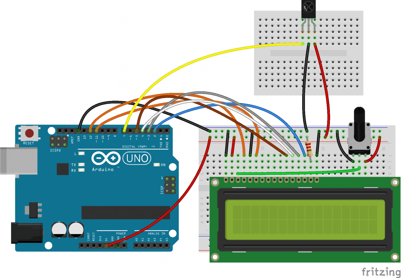
The resistor sets the LCD’s backlight brightness. It can be anything from 200 ohms to about 2K ohms. The potentiometer sets the character contrast. I normally use a 10K ohm potentiometer for this one.
Once everything is connected, upload this code to the Arduino:
#include <IRremote.h>
#include <LiquidCrystal.h>

const int RECV_PIN = 7;
LiquidCrystal lcd(12, 11, 5, 4, 3, 2);
IRrecv irrecv(RECV_PIN);
decode_results results;
unsigned long key_value = 0;

void setup(){
  Serial.begin(9600);
  irrecv.enableIRIn();
  irrecv.blink13(true);
  lcd.begin(16, 2);
}

void loop(){
  if (irrecv.decode(&results)){

        if (results.value == 0XFFFFFFFF)
        results.value = key_value;
        lcd.setCursor(0, 0);
        lcd.clear();

        switch(results.value){
          case 0xFFA25D:
          lcd.print("CH-");
          break;
          case 0xFF629D:
          lcd.print("CH");
          break;
          case 0xFFE21D:
          lcd.print("CH+");
          break;
          case 0xFF22DD:
          lcd.print("|<<");
          break;
          case 0xFF02FD:
          lcd.print(">>|");
          break ;
          case 0xFFC23D:
          lcd.print(">|");
          break ;
          case 0xFFE01F:
          lcd.print("-");
          break ;
          case 0xFFA857:
          lcd.print("+");
          break ;
          case 0xFF906F:
          lcd.print("EQ");
          break ;
          case 0xFF6897:
          lcd.print("0");
          break ;
          case 0xFF9867:
          lcd.print("100+");
          break ;
          case 0xFFB04F:
          lcd.print("200+");
          break ;
          case 0xFF30CF:
          lcd.print("1");
          break ;
          case 0xFF18E7:
          lcd.print("2");
          break ;
          case 0xFF7A85:
          lcd.print("3");
          break ;
          case 0xFF10EF:
          lcd.print("4");
          break ;
          case 0xFF38C7:
          lcd.print("5");
          break ;
          case 0xFF5AA5:
          lcd.print("6");
          break ;
          case 0xFF42BD:
          lcd.print("7");
          break ;
          case 0xFF4AB5:
          lcd.print("8");
          break ;
          case 0xFF52AD:
          lcd.print("9");
          break ;
        }
        key_value = results.value;
        irrecv.resume();
  }
}
Again, if the hex codes don’t match the codes output by your remote, just replace them for each character where it says case 0xXXXXXXXX;.
Using the IR Remote to Control Things
Now I’ll show you a simple demonstration of how you can use the IR remote to control the Arduino’s output pins. In this example, we will light up an LED when a particular button is pressed. You can easily modify the code to do things like control servo motors, or activate relays with any button press from the remote.
The example circuit has the IR receiver connected to the Arduino, with a red LED connected to pin 10 and a green LED connected to pin 11:
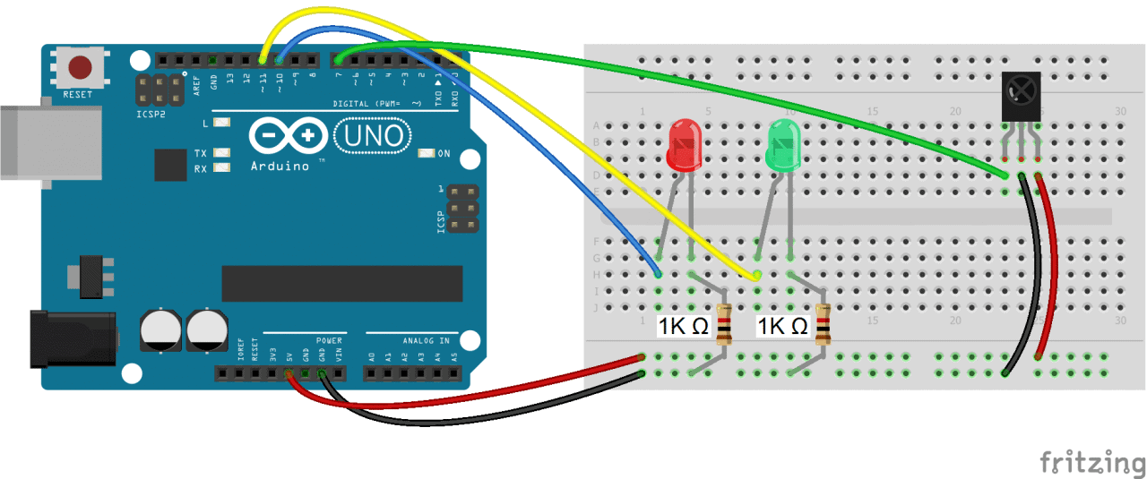
The code below will write digital pin 10 HIGH for 2 seconds when the “5” button is pressed, and write digital pin 11 HIGH for 2 seconds when the “2” button is pressed:
#include <IRremote.h>

const int RECV_PIN = 7;
IRrecv irrecv(RECV_PIN);
decode_results results;
const int redPin = 10;
const int greenPin = 11;


void setup(){
  irrecv.enableIRIn();
  irrecv.blink13(true);
  pinMode(redPin, OUTPUT);
  pinMode(greenPin, OUTPUT);
}

void loop(){
    if (irrecv.decode(&results)){

        switch(results.value){
          case 0xFF38C7: //Keypad button "5"
          digitalWrite(redPin, HIGH);
          delay(2000);
          digitalWrite(redPin, LOW);
          }

        switch(results.value){
          case 0xFF18E7: //Keypad button "2"
          digitalWrite(greenPin, HIGH);
          delay(2000);
          digitalWrite(greenPin, LOW);
          }

        irrecv.resume();
    }
}
So far we have covered the properties of infrared radiation and how communication happens between the transmitter and receiver. We saw how to identify the IR key codes for a given remote control. We learned how to display key presses on serial monitor and on an LCD screen. Finally I showed you how to control the Arduino’s output with the remote. Have fun playing with this and be sure to let us know in the comments if you have any questions or trouble setting this up!


Thank you.
A well presented, informative and useful overview including specific examples for implementation. Bravo.
Thank you this was really helpful. I thought the store where I bought my kits from tempered with my components because my IR receiver didn’t have a board. But now I now it can actually come without a board. Thank you
A very well written and informative article. One thing I would have liked to learn more about is how to choose the IR emitter and receiver. My local store stocks several options of each, does it matter which one I choose?
https://www.fabian.com.mt/en/products/webshop/bycategory/843/name/asc/18/1/infrared–uv-emitters-and-receivers.htm
Well written, clear and concise. Keep it up.
Are the codes complete?
Hello hope that you all are fine. my Ir reciever giving me continous values on serial moniter although i am sending no signals to it. kindly reply.
Thanks
i’m 2 years too late, but you don’t need to type anything in the monitor
hi my receiver gets as hot as the sun and it does not give me any values can you help me
Use 3.3 V instead of 5 V
Mine sizzled for a few seconds. XD
Hi, please i try loading the code on uno and nano board this is the error message (
Build options changed, rebuilding all
C:\Program Files (x86)\Arduino\libraries\RobotIRremote\src\IRremoteTools.cpp:5:16: error: ‘TKD2’ was not declared in this scope
int RECV_PIN = TKD2; // the pin the IR receiver is connected to
^
exit status 1
Error compiling for board Arduino/Genuino Uno.
)
please what should i do , thanks in advance
Hi I’m Savvy I faced the same error too so I installed the IRremote library folder into my Arduino library and it worked the link is above
Hi, late but hopefully still helpful, if not for you maybe for somebody else.
This error-message occurs when you’re using the “Robot IR Remote” library instead of the “IRremote” library, which you would first have to import, either by using the buildt-in feature of the Arduino-IDE, or by downloading a ZIP-archive.
How to remove receiving NEC repeat code. From my remote control it always display 0xFFFFFFFF but when i presses key fast at once it display correct value like 18E7E817 so how to turn off receiving repeat code. Please help.
If you have problems like “error: ‘TKD2’ was not declared in this scope – int RECV_PIN = TKD2; // the pin the IR receiver is connected to” just remove the “RobotIRremote” default library and install the “Arduino-IRremote-master”. Then rename the folder “Arduino-IRremote-master” in “IRremote”. That’s all.
hi,
i connected atmega 328 ic with 4 relayes. really, i made that using two cycles one for the ic and the ir receiver. the cycle was supported using 5v (2 amp) adapter.
The other cycle contained 4 relayes, each one have 1 daiods and 574 transistor. this cycle was supported using 5v (1 amp) adapter.
those cycles were conected from (a)- cathode (b)- the ic’s output pins to the transistors.
the target was to open/close each relay by lg-tv remote control. the cycle work very will through 1 hour from starting point, but after that it hang and not receive the signals.
um looking forward to hearing from you, why this problem is happened.
hi there,
for some reason the program never finishes uploading onto my uno. The program verifies properly and I see some on the memory usage figures but it just never finishes. Any ideas?
Excellent article thank you:)
I’m stuck at the LCD part. I am relatively confident I have connected everything properly, as I have checked and rechecked. However nothing displays on the screen. Is there a way to trouble shoot this?
Thank you,
Colin
Its working now! Sorry, I turned on serial monitor in arduino and it started to work. Coincidence?
Thanks:)
Thx helped me out a lot with my project. Clearly structured and nice to read. Worked like a charm
Hi,
I have been looking for an understandable explanation how to use a IR receiver with Arduino for a while.
Your explanation is the first that is simple and understandable for a beginner.
Thanks to put such good quality information on this site.
Very well written tutorial. Thanks!
Is there a way to speed up the response when the remote button is pushed? There seems to be about a 3-4 second delay between button push and LED response in most cases.
Wow, this was actually exciting and fun.
Each piece of code worked. I could read the codes. It told me the manufacturer.
Now I’m ready to buy a used/discarded remote from a thrift store, map its keys, and use it to drive relays.
Thanks very much for short clear instructions.
My 3 IR receivers are always blinking even before I add the code, and aren’t receiving any data sent from a functional RGB remote controller.
Please, can someone help me?
I have read so many articles or reviews about the blogger
lovers except this post is in fact a nice paragraph, keep it
up. http://www.cardtricksdesigns.com/lva.php
when i try to get the codes for my remote after clicking the serial moniter it automatically starts giving the values why??
Iam building a hand gesture based remote using the ultrasonic sensor.I want to control a music player which already has a remote can anybody help with writting the code.My project is the modification of https://www.instructables.com/id/Ultrasonic-gesture-based-TV-remote-control/
I am keerthy, a student of mechanical engineering. I followed the above said steps everything worked properly except one. In the part of printing the keys to the serial monitor, i had a difficulty. While compiling the codes after changing it according to my remote’s hexadecimal codes, it throws an error saying that the variable is not declared in the scope.
Here is my changed code:
#include
const int RECV_PIN = 7;
IRrecv irrecv(RECV_PIN);
decode_results results;
unsigned long key_value = 0;
void setup(){
Serial.begin(9600);
irrecv.enableIRIn();
irrecv.blink13(true);
}
void loop(){
if (irrecv.decode(&results)){
if (results.value == 0XFFFFFFFF)
results.value = key_value;
switch(results.value){
case 1FE48B7:
Serial.println(“Switch ON/OFF”);
break;
case 1FE58A7:
Serial.println(“Mode”);
break;
case 1FE7887:
Serial.println(“MUTE”);
break;
case 1FE807F:
Serial.println(“>||”);
break;
case 1FE40BF:
Serial.println(“|<>|”);
break ;
case 1FE20DF:
Serial.println(“EQ”);
break ;
case 1FEA05F:
Serial.println(“VOL-“);
break ;
case 1FE609F:
Serial.println(“VOL+”);
break ;
case 1FEE01F:
Serial.println(“0”);
break ;
case 1FE10EF:
Serial.println(“RPT”);
break ;
case 1FE906F:
Serial.println(“U/SD”);
break ;
case 1FE50AF:
Serial.println(“1”);
break ;
case 1FED827:
Serial.println(“2”);
break ;
case 1FEF807:
Serial.println(“3”);
break ;
case 1FE30CF:
Serial.println(“4”);
break ;
case 1FEB04F:
Serial.println(“5”);
break ;
case 1FE708F:
Serial.println(“6”);
break ;
case 1FE00FF:
Serial.println(“7”);
break ;
case 1FEF00F:
Serial.println(“8”);
break ;
case 1FE9867:
Serial.println(“9”);
break ;
}
key_value = results.value;
irrecv.resume();
}
}
And the error says that:
exit status 1
‘IFEFFFFFFFF’ was not declared in this scope
Help me to rectify my mistakes as fast as you can!!!
hi Keerthi , i think the code in your serial monitor is hexa decimal it should change to decimal (hexadecimal to decimal conversion.online converter is available on google.just copy and paste the hexa decimal code in converter and then convert it.copy the converted code and replace that code in your arduino program)…100% working. i already made this..it is useful simple program
Thanks for the tip.Me also faced same issue but now rectified.
Very good explanation and work!
Oops! There is a way using send.Raw.
Very cool!
I would suggest a tutorial to control a led matrix, 8×32, for example, (4 in 1) with this same procedure;
Thank you
Thanks for Sharing this is really informative!!
I find that I often see “FFFFFFFF” when I use some of your code. I added this IF statement around the print statements to omit that:
if(results.value != 4294967295){ // decimal equivalent to 0XFFFFFFFF
ORIGINAL Serial.println OR lcd.print LINE
}
my code error says IRremote.h: No such file or directory can you help me out?
iNSTALL LIBRRARY
https://www.arduinolibraries.info/libraries/i-rremote
Hi, just want to make you my compliments: great turorial, very well explained. Thanks!
Thank you so much for this tutorial. It was clear, concise, and the examples worked.
I had loaded IRrecvDumpV2 into my project, got all needed codes, but could not figure out how to use them to control a homemade arduino robot. Nothing I tried on my own worked.
The IRrecvDumpV2 instructions were saved into the example directories, and was 123 pages long. The doc seemed to be musings of folks who truely live in an embedded world, and went deep into the artistry and wonderment of their cleverness.
Thank you for helping me see the light. These 2 lines are what significantly helped me move forward with my project.
if (results.value == 0XFFFFFFFF)
results.value = key_value;
Thank you, thank you, thank you
Very good job but there s somethng I can’t understand.
When I read the varable ‘results.decode_type’ I get a number from 1 to 7 and not a string like those you use in the program (NEC, SONY …)
switch (results.decode_type){
case NEC: Serial.println(“NEC”); break ;
case SONY: Serial.println(“SONY”); break ;
By the way I use the same Library as you;, results.value codes and the number of bits are perfect
Can you help me?
Thanks
it should be printing unknown if any one of the above is not printing,
Anyway it depends upon which protocol your remote is using like sony,
lg they have their unique protocols . May be your remote is not matching
with the listed strings
Dear sir,
In the scheme ‘Using the IR Remote to Control Things’ the two resistors are connected to the anode. They should be connected to the kathode-side(ground), as I found out.
Thanks for this great tutorial!
Kind regards,
Jan Speyer, the Netherlands
I also found out that on my breadboard the ‘+’ is on the left and the ‘-‘ on the right. Sorry for my comment:-)
Grazie mille, complimenti!!!!!!!!
I am getting this error Message ? This report would have more information with
“Show verbose output during compilation”
enabled in File > Preferences.
Arduino: 1.0.6 (Windows 2000), Board: “Arduino Uno”
In file included from sketch_sep25j.ino:1:
C:\Documents and Settings\HAC\My Documents\Arduino\libraries\Arduino-IRremote-2.6.1\src/IRremote.h:486: error: ISO C++ forbids initialization of member ‘sendPin’
C:\Documents and Settings\HAC\My Documents\Arduino\libraries\Arduino-IRremote-2.6.1\src/IRremote.h:486: error: making ‘sendPin’ static
I am Getting this error ? This report would have more information with
“Show verbose output during compilation”
enabled in File > Preferences.
Arduino: 1.0.6 (Windows 2000), Board: “Arduino Uno”
In file included from sketch_sep25j.ino:1:
C:\Documents and Settings\HAC\My Documents\Arduino\libraries\Arduino-IRremote-2.6.1\src/IRremote.h:486: error: ISO C++ forbids initialization of member ‘sendPin’
C:\Documents and Settings\HAC\My Documents\Arduino\libraries\Arduino-IRremote-2.6.1\src/IRremote.h:486: error: making ‘sendPin’ static
:-) Like it.
Hello,
I’m trying to copy a remote controller of which I have the schematics, but not the parts.
It seems that it’s using the Toshiba protocol, but I can’t find information about it… The part I’m trying to simulate is the PT2248
I had a whole bunch of problems getting the codes to work for my arduino.
the first code, instead of giving me IR codes, it would just print a 0 to the serial port every time i pressed a button on the controller.
the second code didnt work at all…
I tried a number of things, including testing all the different examples in the IRremote library….
after i failed to get it to work seemlessly, i discovered that the IRremote library has been updated in the last few months.
I managed to solve the problem by reverting to an earlier update for the IRremote library (2.7.0), and now everything is working perfectly!
thanks very much!
Hi Daniel
I’ve got the same issue: 0 instead of codes.
Also, I’ve had to delete &results out of ” if (irrecv.decode(&results)){ ” in loop and leave .decode() with nothing in brackets. Have you done the same?
However, you said that swap 3.0.1 to earlier version of IRremote library has solved the issue.
How did you manage it ?
Thanks.
Download the 2.7.0 zip file from
https://www.arduinolibraries.info/libraries/i-rremote
In Arduino IDE:
File>Preferences
copy the sketchbook location
Open File Explorer:
Paste copied sketchbook location address into file explorer
Open libraries
Remove the any previous IRremote folders if there is one
Put the unzipped IRremote-2.7.0 folder into the libraries
Thanks Matt. It works now.👍👍
Hi,
I have read so many blogs but still can’t solve my problem : (
I got different value when I pressed the same button, but I have no idea where the mistakes are.
Hope anyone can help me with my problem, thanks! : )
Here is my code:
#include
int RECV_PIN = 7;
IRrecv irrecv(RECV_PIN);
decode_results results;
void setup(){
Serial.begin(9600);
}
void loop() {
if (irrecv.decode(&results)) {
Serial.println(results.value, HEX);
irrecv.resume();
}
delay(100);
}
P.S. The version of IRremote is 2.7.0
(And sorry for my poor English, I’m not native speaker.)
hi
i need help when ever i try to verify the code it gives me this error message
/tmp/692403348/sketch_apr1a/sketch_apr1a.ino: In function ‘void setup()’:
/tmp/692403348/sketch_apr1a/sketch_apr1a.ino:10:10: error: ‘class IRrecv’ has no member named ‘blink13’
irrecv.blink13(true);
^~~~~~~
exit status 1
i have downloaded the libraries so what is wrong
No they do not work.
Outdated, not compatible with the recent version of the library. Could be interesting to update the code :)
Try commenting out the line
// irrecv.blink13(true);
Worked for me.
While i uploading the code with hide this line // irrecv.blink13(true); sucessfully uploaded but in serial monitor shows error like
The function decode(&results)) is deprecated and may not work as expected! Just use decode() without a parameter and IrReceiver.decodedIRData.
anyone suggest me a good solution to overcome this problem
/*
File name : HX1838_RX.ino
Description : this sketch process HX1838 IR Control signals
emitted at 38 kHz frequency carrier
and detected by VS1838B IR receiver
Author : Anatoly A. Sharapov
Email : a.a.sharapov@gmail.com
Hardware : HX1838 IR Control Module Kit
Vendor URL : https://www.aliexpress.com/item/32562721229.html
Library : IRremote
Lib. version : 3.3.0
Add library : Tools – Manage Libraries
Library URL : https://github.com/Arduino-IRremote/Arduino-IRremote
Example URL : https://www.circuitbasics.com/arduino-ir-remote-receiver-tutorial/
Last revision : 10.01.2022
*/
#include
#include
const uint8_t VS1838B_PIN = 11;
const uint8_t FeedbackLEDPin = 13;
IRrecv irrecv(VS1838B_PIN);
uint32_t IRdecodedRawData; // Up to 32 bit decoded raw data,
// used for sendRaw functions
const bool EnableLEDFeedback = true;
// enable blinking of Feedback LED
void setup() {
Serial.begin(9600); // Init serial
Serial.println(“HX1838_RX.ino is started”);
irrecv.enableIRIn(); // Start the receiver
setLEDFeedback(FeedbackLEDPin, EnableLEDFeedback);
}
void loop() {
if (irrecv.decode()) {
IRdecodedRawData = irrecv.decodedIRData.decodedRawData;
Serial.print(IRdecodedRawData, HEX);
Serial.print(” @ “);
switch (irrecv.decodedIRData.protocol){
case UNKNOWN: Serial.println(“UNKNOWN”); break;
case PULSE_DISTANCE: Serial.println(“PULSE_DISTANCE”); break;
case PULSE_WIDTH: Serial.println(“PULSE_WIDTH”); break;
case DENON: Serial.println(“DENON”); break;
case DISH: Serial.println(“DISH”); break;
case JVC: Serial.println(“JVC”); break;
case LG: Serial.println(“LG”); break;
case LG2: Serial.println(“LG2”); break;
case NEC: Serial.println(“NEC”); break;
case PANASONIC: Serial.println(“PANASONIC”); break;
case KASEIKYO: Serial.println(“KASEIKYO”); break;
case KASEIKYO_JVC: Serial.println(“KASEIKYO_JVC”); break;
case KASEIKYO_DENON: Serial.println(“KASEIKYO_DENON”); break;
case KASEIKYO_SHARP: Serial.println(“KASEIKYO_SHARP”); break;
case KASEIKYO_MITSUBISHI: Serial.println(“KASEIKYO_MITSUBISHI”); break;
case RC5: Serial.println(“RC5”); break;
case RC6: Serial.println(“RC6”); break;
case SAMSUNG: Serial.println(“SAMSUNG”); break;
case SHARP: Serial.println(“SHARP”); break;
case SONY: Serial.println(“SONY”); break;
case ONKYO: Serial.println(“ONKYO”); break;
case APPLE: Serial.println(“APPLE”); break;
case BOSEWAVE: Serial.println(“BOSEWAVE”); break;
case LEGO_PF: Serial.println(“LEGO_PF”); break;
case MAGIQUEST: Serial.println(“MAGIQUEST”); break;
case WHYNTER: Serial.println(“WHYNTER”); break;
default:Serial.println(“default”); break;
}
// Decode
/*
if(IRdecodedRawData == 0xFFA25D) Serial.println(“Pressed 1”);
if(IRdecodedRawData == 0xFF629D) Serial.println(“Pressed 2”);
if(IRdecodedRawData == 0xFFE21D) Serial.println(“Pressed 3”);
if(IRdecodedRawData == 0xFF22DD) Serial.println(“Pressed 4”);
if(IRdecodedRawData == 0xFF02FD) Serial.println(“Pressed 5”);
if(IRdecodedRawData == 0xFFC23D) Serial.println(“Pressed 6”);
if(IRdecodedRawData == 0xFFE01F) Serial.println(“Pressed 7”);
if(IRdecodedRawData == 0xFFA857) Serial.println(“Pressed 8”);
if(IRdecodedRawData == 0xFF906F) Serial.println(“Pressed 9”);
if(IRdecodedRawData == 0xFF9867) Serial.println(“Pressed 0”);
if(IRdecodedRawData == 0xFF6897) Serial.println(“Pressed *”);
if(IRdecodedRawData == 0xFFB04F) Serial.println(“Pressed #”);
if(IRdecodedRawData == 0xFF18E7) Serial.println(“Pressed Arrow Up”);
if(IRdecodedRawData == 0xFF4AB5) Serial.println(“Pressed Arrow Down”);
if(IRdecodedRawData == 0xFF10EF) Serial.println(“Pressed Arrow Left”);
if(IRdecodedRawData == 0xFF5AA5) Serial.println(“Pressed Arrow Right”);
if(IRdecodedRawData == 0xFF38C7) Serial.println(“Pressed Ok”);
*/
irrecv.resume(); // Receive the next value
}
}
“IRremote.h” where to find the library. editor says this.
C:\Users\thiva\AppData\Local\Temp\.arduinoIDE-unsaved2023326-25928-8331dh.pit1g\sketch_apr26a\sketch_apr26a.ino:1:10: fatal error: IRremote: No such file or directory
#include
^~~~~~~~~~
compilation terminated.
exit status 1
Compilation error: IRremote: No such file or directory
You may want to update your tutorial. Currently, when opening the serial monitor, I get the following warning:
Thank you for using the IRremote library!
It seems, that you are using a old version 2.0 code / example.
This version is no longer supported!
Please use one of the new code examples from the library,
available at “File > Examples > Examples from Custom Libraries / IRremote”.
Or downgrade your library to version 2.6.0.
to all my future homies, use IR library 2.5 and it will work as intended.
awesome
Профессиональный сервисный центр по ремонту бытовой техники с выездом на дом.
Мы предлагаем:сервис центры бытовой техники москва
Наши мастера оперативно устранят неисправности вашего устройства в сервисе или с выездом на дом!