DSLR cameras capture incredible photos, and they can store thousands of images on a micro SD card no bigger than a fingernail. Modern smartphone cameras can take and save high-quality images as well, but users can’t select the appropriate lens for a situation and control the aperture, shutter speed, and ISO setting directly. Features like these give skilled DSLR users the ability to set up a shot to their exact specifications. These cameras are also compatible with a wide variety of accessories like intervalometers, which release the camera’s shutter at controlled intervals.

If you’ve ever seen a video with stars moving across the night sky, or a seed germinating and growing into a young plant, then you have seen an intervalometer in action. This style of photography is called time-lapse. Still images taken from a DSLR and intervalometer can be imported into video editing programs to make stunning time-lapse videos.
On many cameras, a versatile 2.5 mm stereo jack forms the intervalometer interface, with plug sections corresponding to ground (base), auto-focus (middle/ring), and shutter release (tip). See How to Hack a Headphone Jack for more info about wiring stereo jacks.
To remotely trigger the device, the photographer connects the camera’s ground to the shutter release. These cameras provide the perfect platform for hacking with an Arduino or similar development board. We successfully tested our Arduino Nano intervalometer on a Canon T2i DSLR, but we’re confident that this device would pair easily with many other DSLRs.
Intervalometer Build
For this build, you’ll need the following parts:
- Arduino Nano, or the development board of your choice
- 4-position DIP switch
- PC817 opto-isolator
- 50 to 200 Ohm resistor
- Double coin cell (or other 6V) battery pack
- 2.5 mm wired stereo plug
- 3D-printed base
- Zip-ties
- Hot glue gun
- Hookup wire
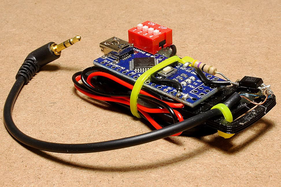
We chose the ubiquitous Arduino Nano for its impressive control, along with a 4-position DIP switch that functions as the user interface. It’s tempting to take the easy route by hooking the Arduino output to the shutter release pin or using a transistor arrangement, but to fully isolate the camera’s electronics, I used a PC817 opto-isolator. Opto-isolators work much like relays, but instead of mechanical switching, the control hardware (the Arduino in this case) powers an LED inside the chip. The emitted light then switches an entirely isolated circuit (the camera) via a phototransistor. See below for an image of the completed circuit design.
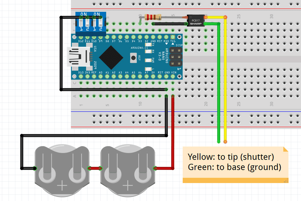
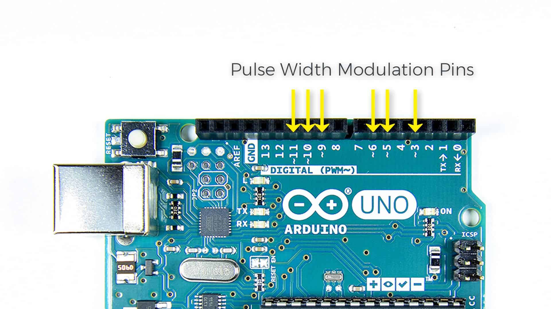
You’ll need to place a small resistor between the Arduino output (digital pin 3) and the opto-isolator to avoid overpowering its internal LED. We used a roughly 50 ohm resistor, but one in the 100-200 ohm range should also work well. Also, we linked the input switches – which conveniently fit into the Nano’s pin spacing – to ground. Linking the switches to ground allows us to use the microcontroller’s internal resistor to hold the inputs high until the switch closes, therefore avoiding any “floating” inputs before or after we activate the switches.
You can lay out this design on a basic breadboard, but to make it durable and portable, we designed a 3D-printed base for the intervalometer, which is available here. Next, we use hot glue to adhere the Nano to the top and the dual CR-2032 battery pack to the bottom. We add a zip-tie for extra support.
Here’s one important note: one side of the build features a pair of rectangular cutouts, designed to add the opto-isolator—via more hot glue—and the shutter release cable to the camera. After soldering the appropriate cables to the opto-isolator, use another zip-tie to secure the cable in place and eliminate any strain.
Programming the Intervalometer
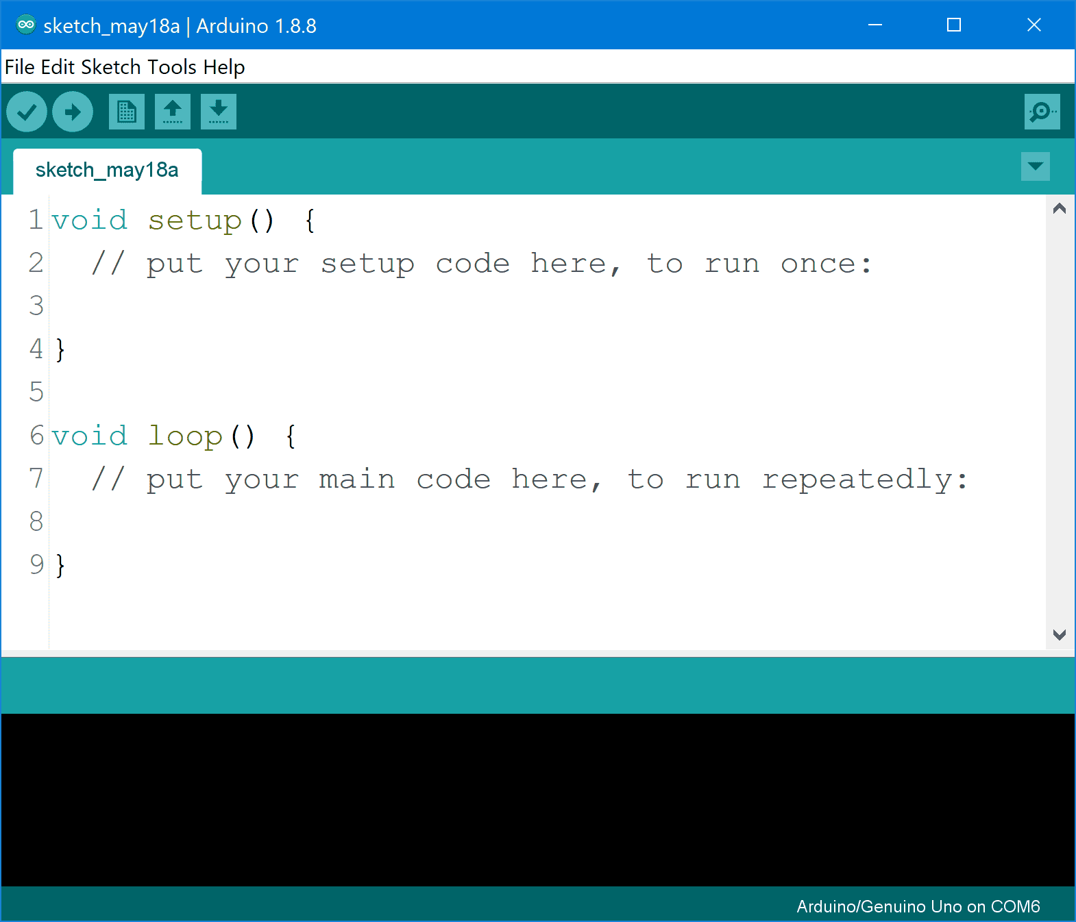
After building the intervalometer, upload this code to your Arduino:
//DIP Switch Intervalometer
//By Jeremy S. Cook

int DIP9 = 0;
int DIP10 = 0;
int DIP11 = 0;
int DIP12 = 0;

void setup() {
  Serial.begin(9600);
  pinMode(3, OUTPUT); //Pin 3 triggers camera via opto-isolator
  pinMode(LED_BUILTIN, OUTPUT); //Output to LED for testing - optional

  pinMode(9, INPUT_PULLUP); //5 second input (pullups result in switch on = low)
  pinMode(10, INPUT_PULLUP); //10 second input
  pinMode(11, INPUT_PULLUP); //30 second input
  pinMode(12, INPUT_PULLUP); //60 second input
}

// the loop function runs over and over again forever
void loop() {
  DIP9 = digitalRead(9);
  DIP10 = digitalRead(10);
  DIP11 = digitalRead(11);
  DIP12 = digitalRead(12);

  Serial.println(DIP9);
  Serial.println(DIP10);
  Serial.println(DIP11);
  Serial.println(DIP12);

  if (DIP9 == LOW || DIP10 == LOW || DIP11 == LOW || DIP12 == LOW){
    digitalWrite(3, HIGH);
    digitalWrite(LED_BUILTIN, HIGH);
    Serial.println("trigger active");
    delay(150);
    digitalWrite(3, LOW);
    Serial.println("trigger off");
    digitalWrite(LED_BUILTIN, LOW); //LED may be omitted if expedient (low light, etc)
  }
  if (DIP9 == LOW) delay(4850); //5 second delay
  if (DIP10 == LOW) delay(10000); //10 second delay
  if (DIP11 == LOW) delay(30000); //30 second delay
  if (DIP12 == LOW) delay(60000); //60 second delay
  //note delay values do not account for 150ms trigger delay w/o DIP9 enabled
}
The code operates as follows:
- The program checks the state of pins 9 through 12, using
INPUT_PULLUPto take advantage of the internal resistors, as we noted earlier. - If any pin is LOW, indicating an on state, it then triggers the shutter for 0.1 seconds.
- The program remains off for a period dictated by the actual switch readings. As programmed, pin 9 gives a 5 second delay, pin 10 gives a 10 second delay, pin 11 gives a 30 second delay, and pin 12 gives a 60 second delay. Each pin adds to the next, so for example, if pins 9 and 12 are switched on, you’ll experience a delay of 65 seconds between each shot. More precisely, this would be 65.1 seconds, accounting for the 0.1 second trigger open time.
- If you want a longer or shorter interval, you can change the delay time for each one of the DIP switches in the
delay()functions in lines 39 to 42. The delay time is in milliseconds.
Operating the Intervalometer
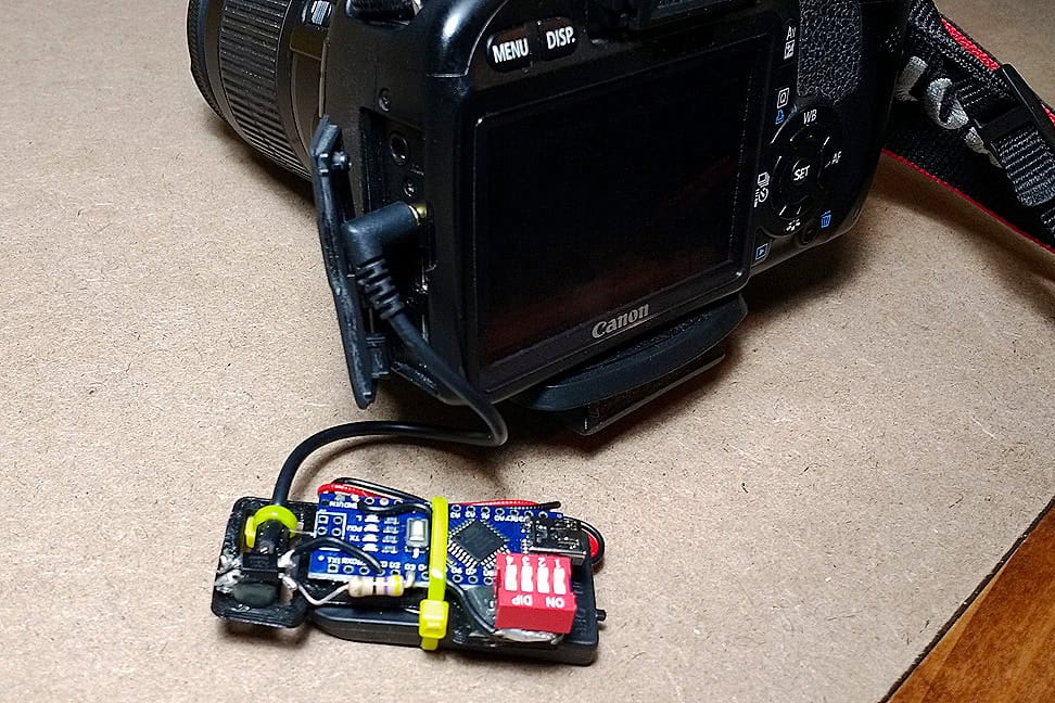
With the programming complete, you’re almost ready to plug the device into your camera and start shooting. One last step: to focus on your subject, turn off the auto-focus on your lens. The auto-focus setting can cause some issues when only using the release pin in this manner, but you likely won’t need to auto-focus between shots when shooting a time-lapse sequence anyway.
Going Further
The Arduino Nano intervalometer makes for a compact device, one that’s easy to (gently) toss into your camera bag for impromptu time-lapse sequences. Using an Arduino in this way gives you a wide range of camera control options. You may choose to change the timing sequence around or change how long the shutter stays open in “bulb” mode. You can even add a sensor to detect light, noise, or other types of stimulus, giving the Arduino Nano intervalometer abilities way beyond a simple timing mechanism.


Hey cool project. I was thinking that if I set the delay longer than 150ms after setting pin3 high it would keep the shutter open for the duration of the delay but that does not seem to be the case. How would you go about taking long exposure shots?
Never mind… it looks like that would be a combination of triggering the shutter and setting the exposure time on the camera.
Great tutorial! I’m wondering what kind of battery life you get from it, and if you’ve ever used it outside?
hi, I have a problem with a project silimar to yours. Can you help?