Home automation is becoming more of a reality as sensors and devices get smaller and more capable. A simple home automation system could detect the temperature and humidity in a room and turn on a fan if it gets too hot. Or it could interface with a motion sensor to turn on a light or unlock a door when a person is present.

In this article, we are going to use the Raspberry Pi as a home automation hub. We will connect two sensors and a 5V relay to wireless modules that can be placed around the house. The Raspberry Pi will receive sensor data from each sensor and print out the results to a central dashboard that can be accessed by any web browser. The wireless 5V relay module can be controlled by a switch on the dashboard.
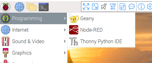
To build the home automation hub, we will need to install and configure several different programs. Let’s start by installing Node-RED
Node-RED
Node-RED is an open-source programming tool that allows visual coding using nodes. Nodes are code blocks that perform a specific function such as input, output, or processing. Furthermore, these nodes can be wired together to do more advanced stuff like visualizing data or receiving data with different protocols like MQTT.
In Node-RED, these connected nodes are called flows.
Installing Node-RED
To install Node-RED, enter the command below in the Raspberry Pi terminal.
bash <(curl -sL https://raw.githubusercontent.com/node-red/linux-installers/master/deb/update-nodejs-and-nodered)Starting Node-RED
After installing, Node-RED will be available in your Raspberry Pi’s desktop menu.
Alternatively, you can start the service from the terminal with:
node-red-pi --max-old-space-size=256Press CTRL+ALT+C or close the terminal to stop Node-RED.
Running Node-RED as a Service
We are going to use the Raspberry Pi as an autonomous home automation hub. To do this, we need to setup Node-RED as a service, so that it will run in the background automatically on boot.
The following commands are provided to work with the service:
node-red-start– starts the Node-RED servicenode-red-stop– stops the Node-RED servicenode-red-restart– restarts the Node-RED servicenode-red-log– displays the Node-RED log
To start Node-RED automatically on boot, enter the following into your terminal:
sudo systemctl enable nodered.serviceTo disable it, simply enter:
sudo systemctl disable nodered.serviceOpening the Node-RED Editor
The Node-RED editor can be accessed with a web browser from any device connected to the same network as the Raspberry Pi. To access the Node-RED editor, enter this into the address bar of a web browser:
http://localhost:1880To find your Raspberry Pi’s IP address, enter hostname -I or ifconfig into the terminal. The address will be shown in the WLAN section.
Installing the Node-RED Dashboard
The Node-RED dashboard is a module that provides a set of nodes in Node-RED to quickly create a live data dashboard. This will serve as the GUI of your home automation hub.
To install the Node-RED dashboard on your Raspberry Pi, enter:
node-red-stop
cd ~/.node-red
npm install node-red-dashboard
Now restart the Raspberry Pi.
sudo rebootTo open the dashboard, type the Raspberry Pi’s IP address in a web browser followed by :1880/ui as shown below:
http://Your_RPi_IP_address:1880/uiInstalling MQTT
MQTT stands for MQ Telemetry Transport. It is lightweight publish and subscribe system where you can publish and receive messages as a client. It is a simple messaging protocol designed for devices like the Raspberry Pi.
Installing Mosquitto Broker
In MQTT, the broker is what’s responsible for receiving and filtering messages, deciding who is interested in them and then publishing the message to all subscribed clients.
There are several brokers you can use. In this tutorial, we’re going to use Mosquitto Broker.
First, enter these commands into the terminal:
sudo apt update
sudo apt install -y mosquitto mosquitto-clients
Press Y to proceed with the installation then wait for it to finish.
Enter the command below to autostart Mosquitto on boot. Lastly, restart the Raspberry Pi.
sudo systemctl enable mosquitto.serviceRun the following command to test if the program is successfully installed.
mosquitto -vThis returns the version of Mosquitto you have in your system. It also tries to reinitialize the program so if it is already running, it will return an error message. If you see it, don’t worry as the program is already installed properly.
The Raspberry Pi Home Automation Hub
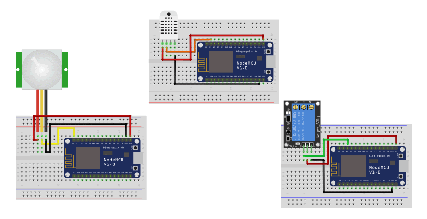
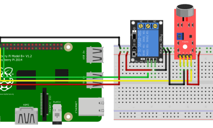
Our goal is to have a Raspberry Pi control three ESP8266 WiFi shields. The WiFi shields will be connected to a PIR motion sensor, a DHT22 temperature and humidity sensor, and a 5V relay. A software called NodeMCU will be installed on each WiFi shield that will allow the Raspberry Pi to communicate with each WiFi sheild wirelessly.
What you need:
- Raspberry Pi
- Raspberry Pi power supply
- Three breadboards
- Jumper wires
- ESP8266 WiFi module
- SRD-05VDC-SL-C 5V relay
- DHT22 humidity and temperature sensor
- PIR motion sensor
Connect the components as shown below (Raspberry Pi not shown):
Create the Node-RED Dashboard
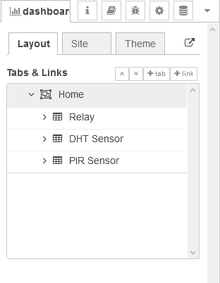
Open the Node-RED editor. In the top right corner, open the dashboard tab. Now click on the Layout tab. Create a tab called Home, then create three groups: Relay, DHT Sensor, and PIR Sensor:
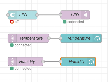
Make a Flow
Drag the nodes to the workspace. You can find all of the available nodes on the left side of your editor.
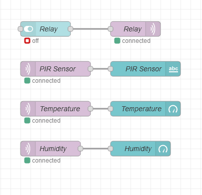
The switch node will determine the message Node-RED will send. Then, the MQTT output node will publish the message according to the switch’s state, turning the LED on or off.
On the other hand, the three MQTT input nodes are subscribed to the air, temperature, and humidity topics. These nodes will fetch the data and send it to the text and gauge node to display the text alert and values.
Connecting Node-RED to Mosquitto
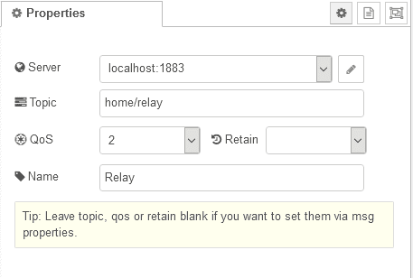
To establish the wireless connection between the Raspberry Pi and NodeMCU, we need to connect Node-RED and the MQTT broker, Mosquitto. Double click the MQTT output node:
Click the Add new mqtt-broker option.
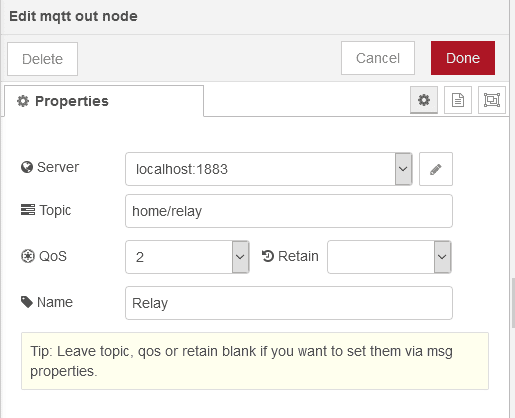
Type localhost in the server field:
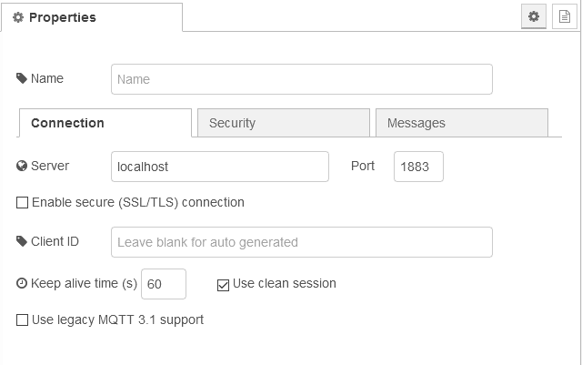
This will add the broker to the other nodes as well.
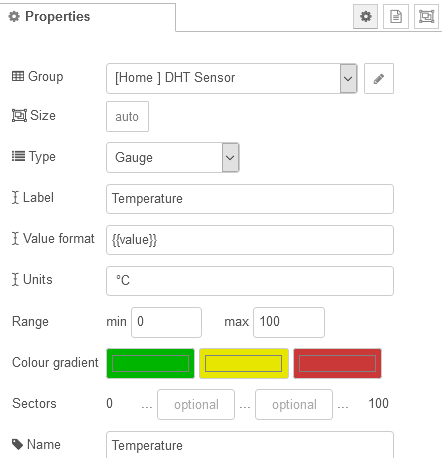
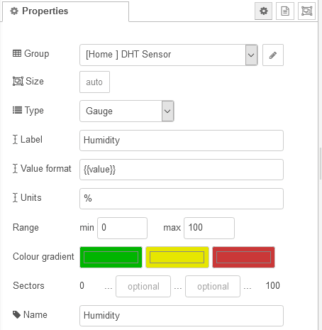
Configuring the Nodes
You can change the label, unit, topic and more of each node.
- Switch
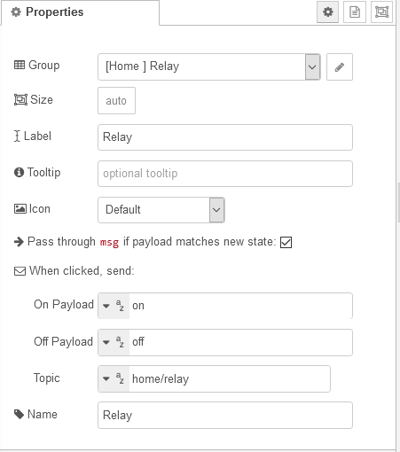
- MQTT Output Node
- MQTT Input Node (PIR Sensor)
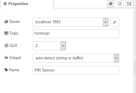
- Text
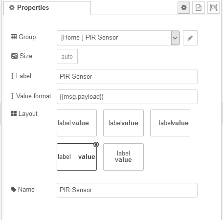
- MQTT Input Node (Temperature)
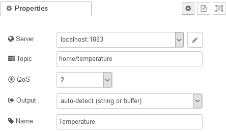
- Gauge (Temperature)
- MQTT Input Node (Humidity)
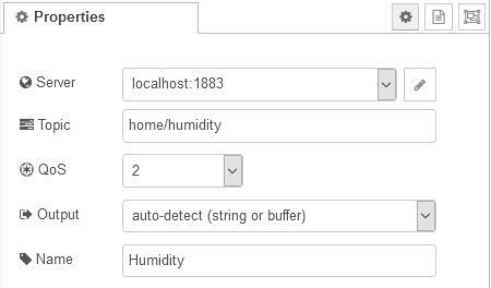
- Gauge (Humidity)
Click and drag the end of the first node to the next node to connect them.
Now, to apply the changes and display them into your dashboard, click the Deploy button on the top right corner.
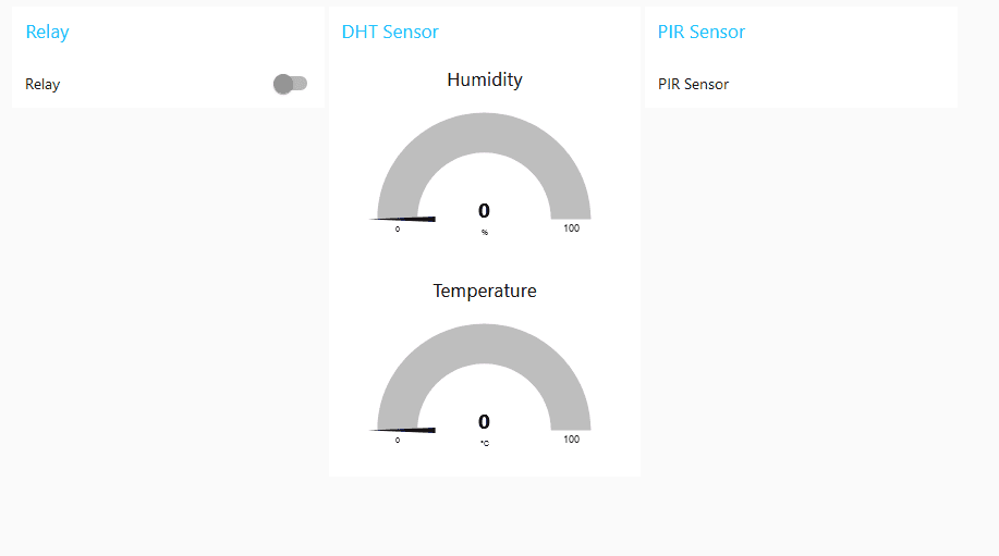
Visit the Node-RED dashboard to view the switches and gauges. Everything is still blank because we haven’t setup NodeMCU yet:
Preparing the Arduino IDE
We are going to use the Arduino IDE to program the NodeMCU. First, install the required libraries: PubSubClient by Nick O’Leary and DHT Sensor by Adafruit.
The PubSubClient library provides the client with easy publish/subscribe messaging with a server that supports MQTT. On the other hand, the DHT sensor library allows the user to interface any DHT sensor to read temperature and humidity with an Arduino compatible board.
To install libraries in the IDE, open the Library Manager under Tools. You can also use the shortcut CTRL+SHIFT+I. Search for the name of the library in the manager and click install.
After installing the libraries, restart the program. Then, go to Tools. Inside boards, select NodeMCU 1.0 (ESP-12E Module). After that, choose the port number of your device in Tools > Port > COM7 (in my case).
Code for PIR Sensor WiFi Module
Using the Arduino IDE, upload this code to the PIR sensor’s ESP8266 WiFi module. This program will read the PIR sensor once every 250 milliseconds.
If the value is 0, the loop will continue, but if the value is 1, it will send a string message to your NodeRED dashboard that a motion has been detected.
At the top of each program below, change the ssid (WiFi network name), password, and mqtt_server (IP number of the Raspberry Pi) to your own values.
#include <ESP8266WiFi.h>
#include <PubSubClient.h>

const char* ssid = "HUAWEI-6HxE";
const char* password = "K4H9khUh";
const char* mqtt_server = "192.168.100.23";

WiFiClient espClient;
PubSubClient client(espClient);

const int PIR = D0;

long now = millis();
long lastMeasure = 0;

void setup() {
  pinMode(PIR, INPUT);
  Serial.begin(115200);
  delay(10);

  Serial.println();

  Serial.print("Connecting to ");
  Serial.println(ssid);
  WiFi.begin(ssid, password);

  while (WiFi.status() != WL_CONNECTED) {
    delay(500);
    Serial.print(".");
  }

  Serial.println("");
  Serial.print("WiFi connected - ESP IP address: ");
  Serial.println(WiFi.localIP());
  client.setServer(mqtt_server, 1883);
}

void loop() {

  if (!client.connected()) {
    while (!client.connected()) {
    Serial.print("Attempting MQTT connection...");

    if (client.connect("ESP8266Client")) {
      Serial.println("connected");
    } else {
      Serial.print("failed, rc=");
      Serial.print(client.state());
      Serial.println(" try again in 5 seconds");
      delay(5000);
    }
   }
 }
  if(!client.loop())
    client.connect("ESP8266Client");

  now = millis();

  if (now - lastMeasure > 250) {

    lastMeasure = now;

    int pirstate = digitalRead(PIR);

    if (pirstate == 1) {
      String alertmessage = "Motion Detected!";
      client.publish("home/pir", alertmessage);
    }
    Serial.print("PIR State: ");
    Serial.println(PIR);
  }
}
Code for DHT22 Sensor WiFi Module
Now upload this code to the WiFi module connected to the DHT22 sensor. This code reads the temperature and humidity readings every two seconds and publishes the values in the home/temperature and home/humidity topics via MQTT.
#include <ESP8266WiFi.h>
#include <PubSubClient.h>
#include "DHT.h"

#define DHTTYPE DHT11

const char* ssid = "HUAWEI-6HxE";
const char* password = "K4H9khUh";
const char* mqtt_server = "192.168.100.23";

WiFiClient espClient;
PubSubClient client(espClient);

const int DHTPin = D1;

DHT dht(DHTPin, DHTTYPE);

long now = millis();
long lastMeasure = 0;

void setup() {
  dht.begin();
  Serial.begin(115200);

  delay(10);

  Serial.println();
  Serial.print("Connecting to ");
  Serial.println(ssid);
  WiFi.begin(ssid, password);

  while (WiFi.status() != WL_CONNECTED) {
    delay(500);
    Serial.print(".");
  }

  Serial.println("");
  Serial.print("WiFi connected - ESP IP address: ");
  Serial.println(WiFi.localIP());
  client.setServer(mqtt_server, 1883);
}

void loop() {

  if (!client.connected()) {
    while (!client.connected()) {
    Serial.print("Attempting MQTT connection...");

    if (client.connect("ESP8266Client")) {
      Serial.println("connected");
    } else {
      Serial.print("failed, rc=");
      Serial.print(client.state());
      Serial.println(" try again in 5 seconds");
      delay(5000);
    }
   }
 }
  if(!client.loop())
    client.connect("ESP8266Client");

  now = millis();
  if (now - lastMeasure > 2000) {
    lastMeasure = now;
    float h = dht.readHumidity();
    float t = dht.readTemperature();

    if (isnan(h) || isnan(t)) {
      Serial.println("Failed to read from DHT sensor!");
      return;
    }

    static char temperatureTemp[7];
    dtostrf(t, 6, 2, temperatureTemp);
    static char humidityTemp[7];
    dtostrf(h, 6, 2, humidityTemp);

    client.publish("home/temperature", temperatureTemp);
    client.publish("home/humidity", humidityTemp);

    Serial.print("Humidity: ");
    Serial.println(h);
    Serial.print(" %\t Temperature: ");
    Serial.println(t);
  }
}
Code for 5V Relay WiFi Module
Finally, upload this code to the WiFi module that has the 5V relay connected to it. This code subscribes the WiFi module to the home/relay topic.
If the switch on your NodeRED dashboard is toggled to HIGH or ON, the relay will be activated. Similarly, if it is toggled to LOW or OFF, the relay will shut off.
#include <ESP8266WiFi.h>
#include <PubSubClient.h>

const char* ssid = "HUAWEI-6HxE";
const char* password = "K4H9khUh";
const char* mqtt_server = "192.168.100.23";

WiFiClient espClient;
PubSubClient client(espClient);

const int relay = D2;

void callback(String topic, byte* message, unsigned int length) {
  Serial.print("Message arrived on topic: ");
  Serial.print(topic);
  Serial.print(". Message: ");
  String messageTemp;

  for (int i = 0; i < length; i++) {
    Serial.print((char)message[i]);
    messageTemp += (char)message[i];
  }
  Serial.println();

  if(topic=="home/relay"){
      Serial.print("Changing relay to ");
      if(messageTemp == "on"){
        digitalWrite(relay, HIGH);
        Serial.print("On");
      }
      else if(messageTemp == "off"){
        digitalWrite(relay, LOW);
        Serial.print("Off");
      }
  }
  Serial.println();
}

void setup() {
  pinMode(relay, OUTPUT);
  Serial.begin(115200);

  delay(10);

  Serial.println();
  Serial.print("Connecting to ");
  Serial.println(ssid);
  WiFi.begin(ssid, password);

  while (WiFi.status() != WL_CONNECTED) {
    delay(500);
    Serial.print(".");
  }

  Serial.println("");
  Serial.print("WiFi connected - ESP IP address: ");
  Serial.println(WiFi.localIP());
  client.setServer(mqtt_server, 1883);
  client.setCallback(callback);

}

void loop() {

  if (!client.connected()) {
    while (!client.connected()) {
    Serial.print("Attempting MQTT connection...");

    if (client.connect("ESP8266Client")) {
      Serial.println("connected");
      client.subscribe("home/relay");
    } else {
      Serial.print("failed, rc=");
      Serial.print(client.state());
      Serial.println(" try again in 5 seconds");
      delay(5000);
    }
   }
 }
  if(!client.loop())
    client.connect("ESP8266Client");
}
Again, don’t forget to change the ssid (WiFi network name), password, and mqtt_server (IP number of the Raspberry Pi) at the top of each sketch to your own values.
Now open a browser and visit the Node-RED dashboard. You should see the DHT22 sensor’s temperature and humidity data being displayed. If you wave your hand over the PIR sensor, you should get a notification that motion was detected. You can also control the 5V relay by clicking the toggle switch.
Thanks for reading! Feel free to leave a comment below if you have questions about anything.


Impressive article… Explained well 🤩🤩🤩
installed Raspbian on new RPi 4 and executed the Node-RED install script.
Th script returns following message:
—
Running Node-RED install for user pi at /home/pi on raspbian
You can force an install of node 12 or 14 by using the –node12 or –node14 parameter
However doing so may break some nodes that may need re-installing manually.
Generally it is recommended to upgrade all nodes to their latest versions before upgrading.
Please backup your installation and flows before upgrading.
Exiting now.
—
How can i correct this?
Thanks
Jan