Keypads are a great way to let users interact with your project. You can use them to navigate menus, enter passwords, and control games and robots.

In this tutorial, I’ll show you how to setup a keypad on the Arduino. First I’ll explain how the Arduino detects key presses, then I’ll show you how to find the pinout of any keypad. As a simple example, I’ll show you how to print out the key presses on the serial monitor and an LCD. Finally, I’ll show you how to activate a 5V relay when a password is entered correctly.
Watch the video for this tutorial here:
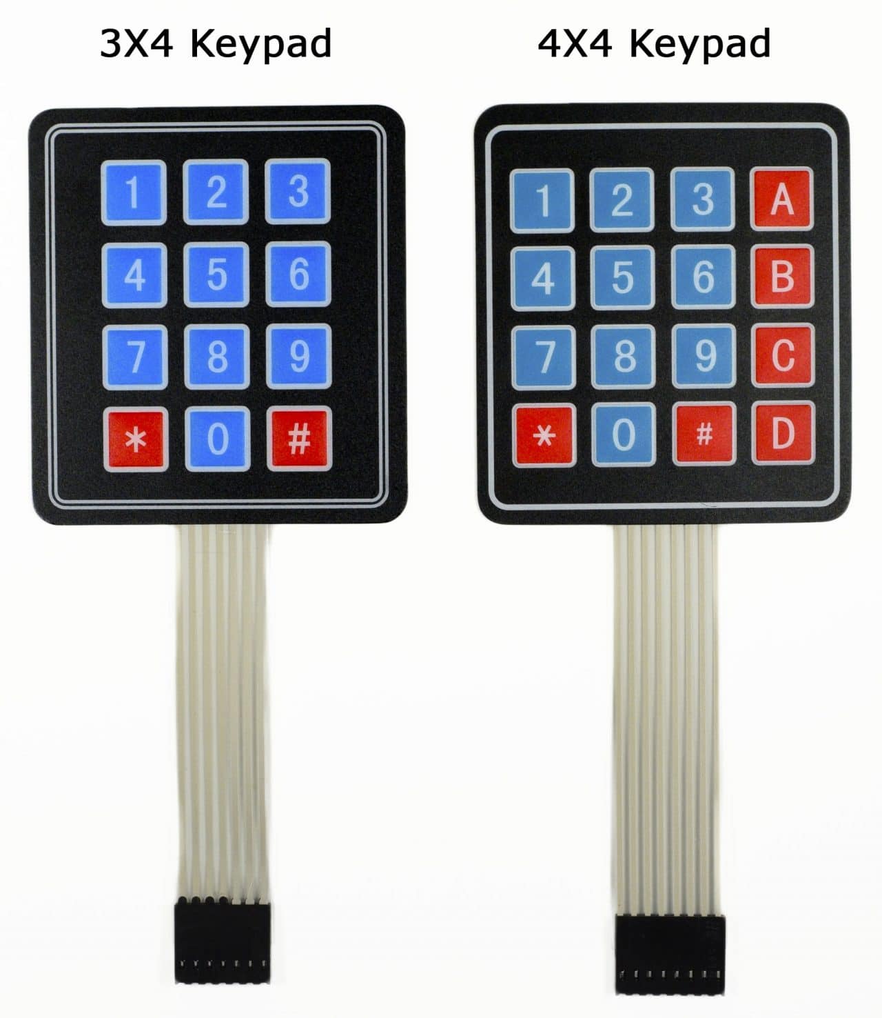
I’ll be using a 4X4 matrix membrane keypad in this article, but there’s also code and wiring diagrams for 3X4 matrix keypads as well. I like membrane style keypads because they’re thin and they also have adhesive backing so you can stick them to most flat surfaces. You can also get telephone style keypads that have thicker buttons if you like that style better. Even salvaged keypads from old telephones will work with the Arduino.
How Keypads Work
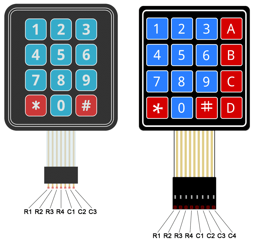
The buttons on a keypad are arranged in rows and columns. A 3X4 keypad has 4 rows and 3 columns, and a 4X4 keypad has 4 rows and 4 columns:
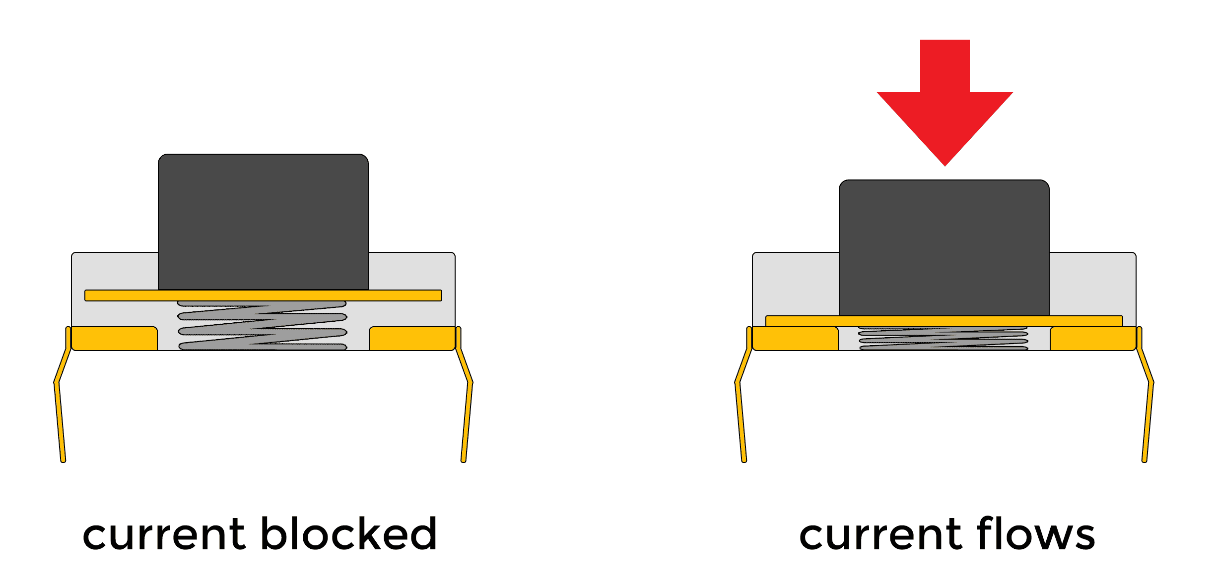
Beneath each key is a membrane switch. Each switch in a row is connected to the other switches in the row by a conductive trace underneath the pad. Each switch in a column is connected the same way – one side of the switch is connected to all of the other switches in that column by a conductive trace. Each row and column is brought out to a single pin, for a total of 8 pins on a 4X4 keypad:
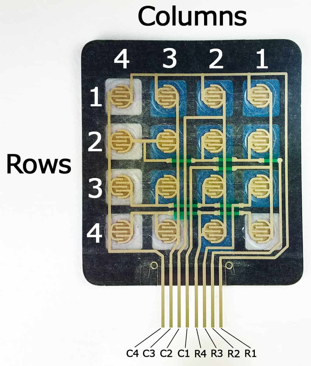
Pressing a button closes the switch between a column and a row trace, allowing current to flow between a column pin and a row pin.
The schematic for a 4X4 keypad shows how the rows and columns are connected:
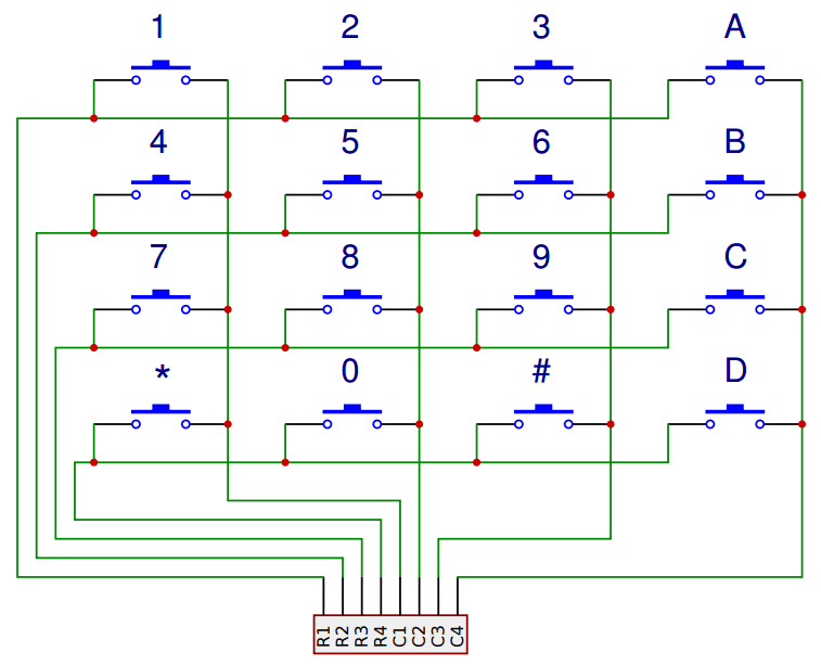
The Arduino detects which button is pressed by detecting the row and column pin that’s connected to the button.
This happens in four steps:
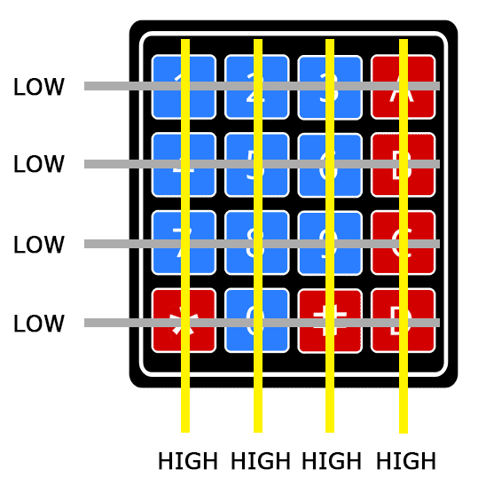
1. First, when no buttons are pressed, all of the column pins are held HIGH, and all of the row pins are held LOW:
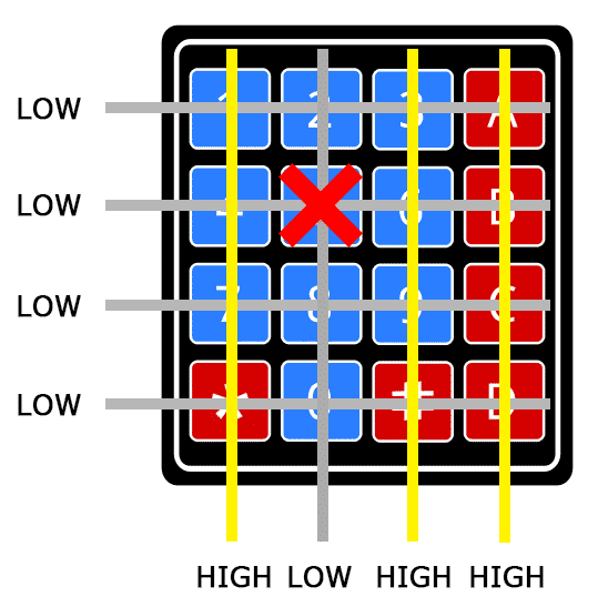
2. When a button is pressed, the column pin is pulled LOW since the current from the HIGH column flows to the LOW row pin:
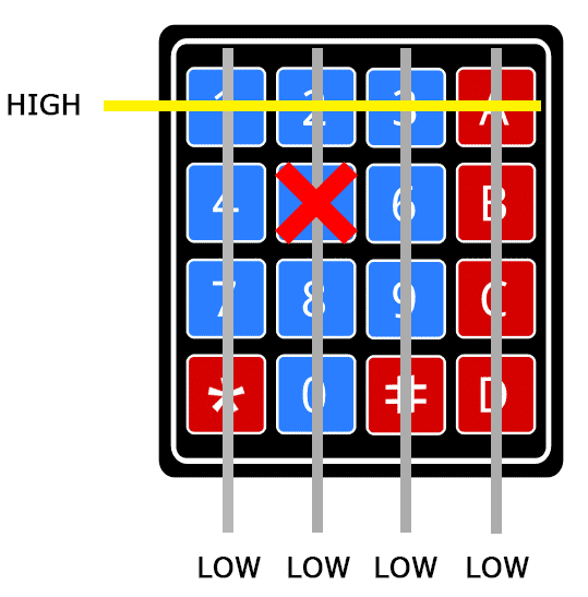
3. The Arduino now knows which column the button is in, so now it just needs to find the row the button is in. It does this by switching each one of the row pins HIGH, and at the same time reading all of the column pins to detect which column pin returns to HIGH:
4. When the column pin goes HIGH again, the Arduino has found the row pin that is connected to the button:
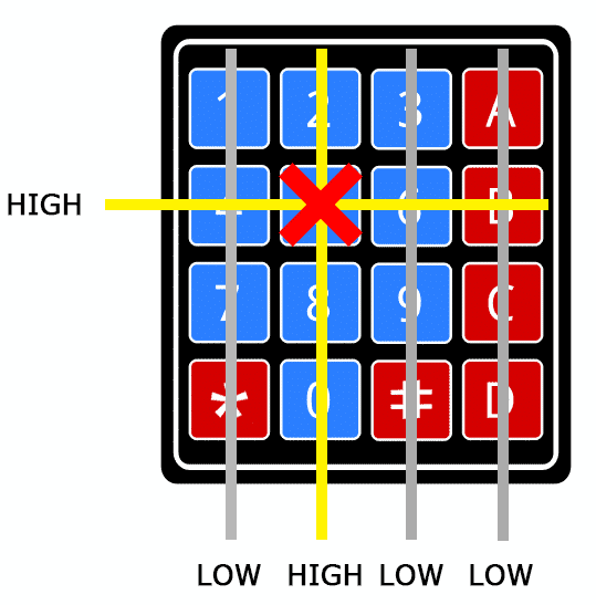
From the diagram above, you can see that the combination of row 2 and column 2 could only mean that the number 5 button was pressed.
Connect the Keypad to the Arduino
The pin layout for most membrane keypads will look like this:
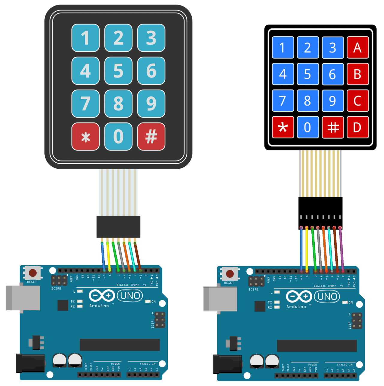
Follow the diagrams below to connect the keypad to an Arduino Uno, depending on whether you have a 3X4 or 4X4 keypad:
How to Find the Pinout of Your Keypad
If your keypad’s pin layout doesn’t match the ones above, you can probe the pins to figure it out. You’ll need to build a test circuit by connecting an LED and a current limiting resistor to the Arduino (or any 5V power source) like this:
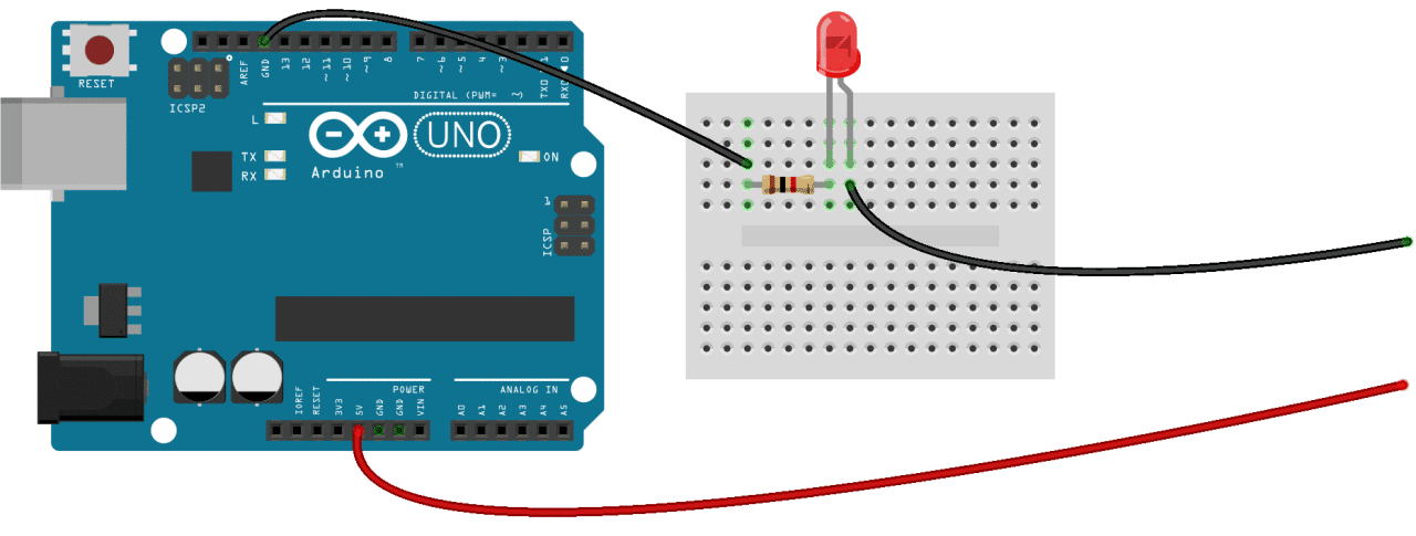
First, find out which keypad pins are connected to the button rows. Insert the ground (black) wire into the first pin on the left. Press any button in row 1 and hold it down. Now insert the positive (red) wire into each one of the other pins. If the LED lights up at one of the pins, press and hold another button in row 1, then insert the positive wire into each one of the other pins again. If the LED lights up on a different pin, it means the ground wire is inserted into the row 1 pin. If none of the buttons in row 1 make the LED light up, the ground wire is not connected to row 1. Now move the ground wire over to the next pin, press a button in a different row, and repeat the process above until you’ve found the pin for each row.
To figure out which pins the columns are connected to, insert the ground wire into the pin you know is row 1. Now press and hold any one of the buttons in that row. Now insert the positive wire into each one of the remaining pins. The pin that makes the LED light up is the pin that’s connected to that button’s column. Now press down another button in the same row, and insert the positive wire into each one of the other pins. Repeat this process for each one of the other columns until you have each one mapped out.
Programming the Keypad
For a basic demonstration of how to setup the keypad, I’ll show you how to print each key press to the serial monitor.
Install the Library
We’ll use the Keypad library by Mark Stanley and Alexander Brevig. This library takes care of setting up the pins and polling the different columns and rows. To install the Keypad library, go to Sketch > Include Library > Manage Libraries and search for “keypad”. Click on the library, then click install.
The Code for a 4X4 Keypad
Once the Keypad library is installed, you can upload this code to the Arduino if you’re using a 4X4 keypad:
#include <Keypad.h>

const byte ROWS = 4;
const byte COLS = 4;

char hexaKeys[ROWS][COLS] = {
  {'1', '2', '3', 'A'},
  {'4', '5', '6', 'B'},
  {'7', '8', '9', 'C'},
  {'*', '0', '#', 'D'}
};

byte rowPins[ROWS] = {9, 8, 7, 6};
byte colPins[COLS] = {5, 4, 3, 2};

Keypad customKeypad = Keypad(makeKeymap(hexaKeys), rowPins, colPins, ROWS, COLS);

void setup(){
  Serial.begin(9600);
}

void loop(){
  char customKey = customKeypad.getKey();

  if (customKey){
    Serial.println(customKey);
  }
}
The Code for a 3X4 Keypad
If you’re using a 3X4 keypad, you can use this code:
#include <Keypad.h>

const byte ROWS = 4;
const byte COLS = 3;

char hexaKeys[ROWS][COLS] = {
  {'1', '2', '3'},
  {'4', '5', '6'},
  {'7', '8', '9'},
  {'*', '0', '#'}
};

byte rowPins[ROWS] = {9, 8, 7, 6};
byte colPins[COLS] = {5, 4, 3};

Keypad customKeypad = Keypad(makeKeymap(hexaKeys), rowPins, colPins, ROWS, COLS);

void setup(){
  Serial.begin(9600);
}

void loop(){
  char customKey = customKeypad.getKey();

  if (customKey){
    Serial.println(customKey);
  }
}
Lines 3 and 4 in the code above set the number of rows and columns on the keypad.
Lines 6-11 define which characters are printed when a particular button is pressed on the keypad. The characters are laid out just as they appear on the keypad. If your keypad has a different layout, you can define which characters are printed when you press a button. For example, say your keypad has a column of letters on the left instead of the right. You would just change it to this:
char hexaKeys[ROWS][COLS] = {
{'A', '1', '2', '3'},
{'B', '4', '5', '6'},
{'C', '7', '8', '9'},
{'D', '*', '0', '#'}
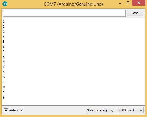
}; After you upload the code, open the serial monitor. When you press a key, the value will be printed out:
Using an LCD with the Keypad
Now let’s see how to print the key presses on an LCD. 4X4 keypads use 8 pins and 3X4 keypads use 7 pins. That takes up a lot of pins, so I’m going to use an I2C enabled LCD because it only needs 4 wires to connect to the Arduino.
Install the LiquidCrystal_I2C Library
To use an I2C enabled LCD on the Arduino, you’ll need to install the LiquidCrystal I2C library by Marco Schwartz. This library is nice because it includes most of the functions available in the standard LiquidCrystal library. To install it, download the ZIP file below, then go to Sketch > Include Library > Add .ZIP Library:
The Wire Library
The Wire library is needed to add support for I2C communication. It comes packaged with the Arduino IDE, so there’s no need to install it. But if for some reason it’s not installed on your system, go to Sketch > Include Library > Manage Libraries and search for “wire” to install it.
Connect the Keypad and LCD
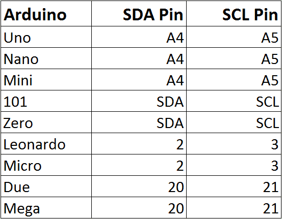
Once the libraries are installed, connect the ground and Vcc pins of the LCD to the Arduino, then connect the LCD’s SDA and SCL pins according to the table below for the different Arduino boards:
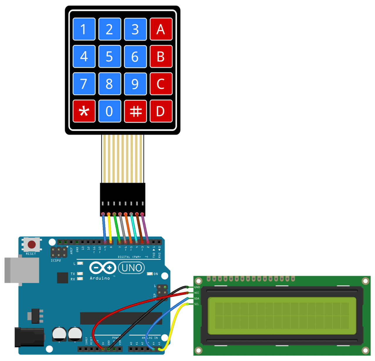
Then connect the keypad to the Arduino. It should look something like this (for an Arduino Uno):
Code for Output to an LCD
Once everything is connected, upload this code to the Arduino:
#include <Wire.h>
#include <LiquidCrystal_I2C.h>
#include <Keypad.h>

const byte ROWS = 4;
const byte COLS = 4;

char hexaKeys[ROWS][COLS] = {
  {'1', '2', '3', 'A'},
  {'4', '5', '6', 'B'},
  {'7', '8', '9', 'C'},
  {'*', '0', '#', 'D'}
};

byte rowPins[ROWS] = {9, 8, 7, 6};
byte colPins[COLS] = {5, 4, 3, 2};

Keypad customKeypad = Keypad(makeKeymap(hexaKeys), rowPins, colPins, ROWS, COLS);

LiquidCrystal_I2C lcd(0x21, 16, 2);

void setup(){
  lcd.backlight();
  lcd.init();
}

void loop(){
  char customKey = customKeypad.getKey();
  if (customKey){
    lcd.clear();
    lcd.setCursor(0, 0);
    lcd.print(customKey);
  }
}
You’ll need to add the I2C address of your LCD on line 20:
LiquidCrystal_I2C lcd(0x21, 16, 2);
The I2C address of my LCD is 0x21, but your’s will probably be different. The I2C address of your LCD should be provided in the datasheet, but if not, you can find it by running this I2C_Scanner sketch.
Use a Password to Activate a Relay
One of the most useful applications of a keypad is to use it for keyed entry. You can set up a password and have the Arduino activate a relay or some other module if the password is correct. The following code will activate a 5V relay when the password is entered correctly:
#include <Wire.h>
#include <LiquidCrystal_I2C.h>
#include <Keypad.h>
#define Password_Length 8
int signalPin = 12;
char Data[Password_Length];
char Master[Password_Length] = "123A456";
byte data_count = 0, master_count = 0;
bool Pass_is_good;
char customKey;
const byte ROWS = 4;
const byte COLS = 4;
char hexaKeys[ROWS][COLS] = {
{'1', '2', '3', 'A'},
{'4', '5', '6', 'B'},
{'7', '8', '9', 'C'},
{'*', '0', '#', 'D'}
};
byte rowPins[ROWS] = {9, 8, 7, 6};
byte colPins[COLS] = {5, 4, 3, 2};
Keypad customKeypad = Keypad(makeKeymap(hexaKeys), rowPins, colPins, ROWS, COLS);
LiquidCrystal_I2C lcd(0x21, 16, 2);
void setup(){
lcd.init();
lcd.backlight();
pinMode(signalPin, OUTPUT);
}
void loop(){
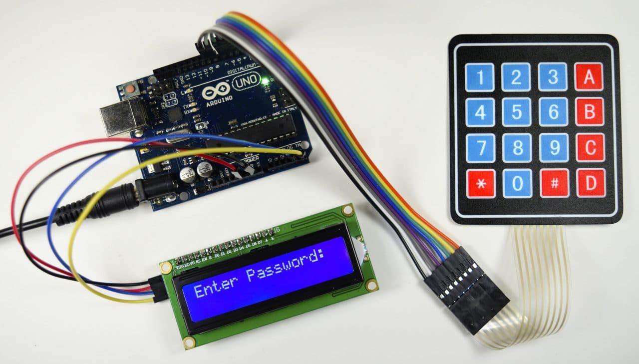
lcd.setCursor(0,0);
lcd.print("Enter Password:");
customKey = customKeypad.getKey();
if (customKey){
Data[data_count] = customKey;
lcd.setCursor(data_count,1);
lcd.print(Data[data_count]);
data_count++;
}
if(data_count == Password_Length-1){
lcd.clear();
if(!strcmp(Data, Master)){
lcd.print("Correct");
digitalWrite(signalPin, HIGH);
delay(5000);
digitalWrite(signalPin, LOW);
}
else{
lcd.print("Incorrect");
delay(1000);
}
lcd.clear();
clearData();
}
}
void clearData(){
while(data_count !=0){
Data[data_count--] = 0;
}
return;
}You can change the password on line 10 by replacing the 123A456 text with your own password:
char Master[Password_Length] = "123A456";
The length of the password needs to be set on line 5:
#define Password_Length 8
The password in the example above is only 7 characters long, but the password length is actually one greater than 7 because there is a null character added to the end of the string. For example, if your password is 5 characters long, you would enter 6 for the password length.
The output pin that activates the relay is defined on line 7:
int signalPin = 12;
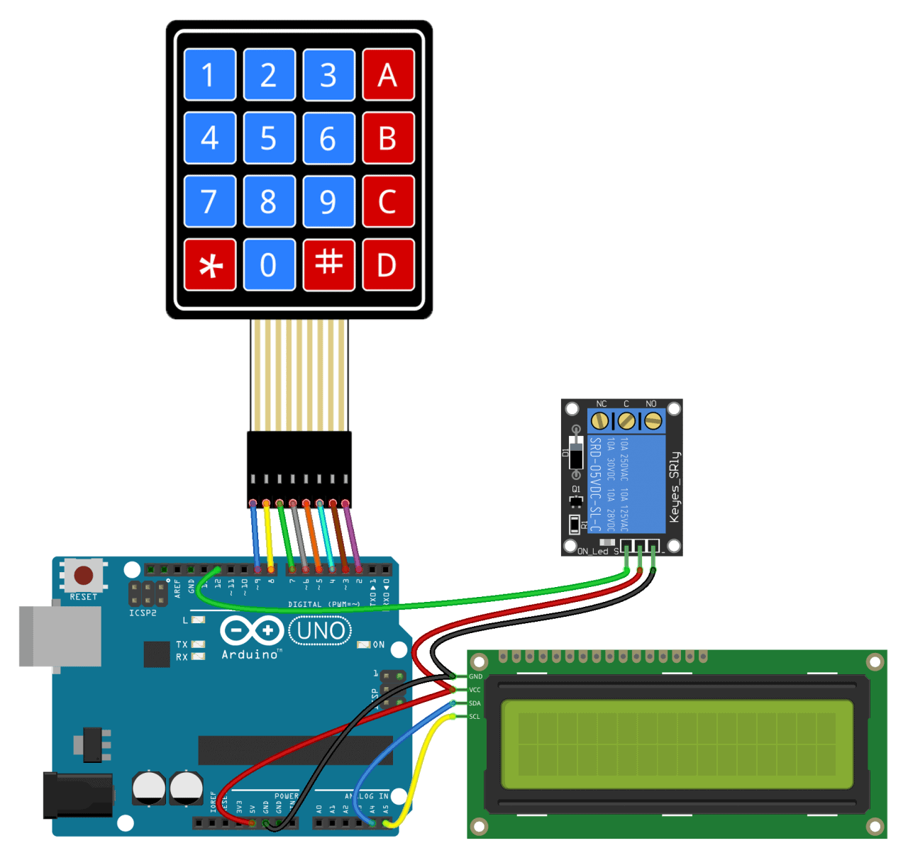
After connecting everything to the Arduino, you should have something that looks like this:
Well that’s about it. It’s not hard to set up a keypad at all. I think with a little trial and error you should be able to modify the code above to work with most of the projects you’d want to use a keypad for. But if you run into problems, just let us know in the comments and we’ll try to help you out.


Hey,
is it possible to get this code working with multiple passwords?
i have the same lcd that you used i this project but there are no pins on the left side of the lcd. please help!
you can use i2c lcd converter to convert 16 pins at lcd to 4 pins here is a link :
https://www.aliexpress.com/item/LCD-2004-IIC-I2C-Interface-adapter-plate-LCD1602-2004/1353322548.html?spm=2114.10010108.1000013.3.48a06c02KpKWdU&gps-id=pcDetailBottomMoreThisSeller&scm=1007.13339.90158.0&scm_id=1007.13339.90158.0&scm-url=1007.13339.90158.0&pvid=d249671f-709e-4fb9-aeec-5e2b3a954526
I love to do this project, but do you have a fail-safe option? something like a bypass for example if the system failed to respond due to unexpected error? loose wire, broken relay, etc… Hope you could me with this.
Peter Giles
can u get the keypad to move the servo WITHOUT the lcd screen
Your keypad arduino was the best i found online.
thanks a lot for all the info
i’ve changed the code, i do not have a display yet, so it prints on the serial monitor.
the pass can be changed using a master password.
#include
//#include
#include
#define Password_Length 4
int signalPin = 13, i=0;
char Data[Password_Length];
char pass[Password_Length] = “111”;
char Master[Password_Length] = “444”;
byte data_count = 0;
bool Pass_is_good;
char customKey;
char newKey;
const byte ROWS = 4;
const byte COLS = 3;
char hexaKeys[ROWS][COLS] = {
{‘1’, ‘2’, ‘3’},
{‘4’, ‘5’, ‘6’},
{‘7’, ‘8’, ‘9’},
{‘*’, ‘0’, ‘#’}
};
byte rowPins[ROWS] = {9, 8, 7, 6};
byte colPins[COLS] = {5, 4, 3};
Keypad customKeypad = Keypad(makeKeymap(hexaKeys), rowPins, colPins, ROWS, COLS);
//LiquidCrystal_I2C lcd(0x21, 16, 2);
void setup(){
//lcd.init();
//lcd.backlight();
Serial.begin(9600);
pinMode(signalPin, OUTPUT);
}
void loop(){
//lcd.setCursor(0,0);
//lcd.print(“Enter Password:”);
//Serial.print(“Enter Password: “);
customKey = customKeypad.getKey();
if (customKey){
Data[data_count] = customKey;
//lcd.setCursor(data_count,1);
Serial.print(Data[data_count]);
//lcd.print(Data[data_count]);
data_count++;
}
if(data_count == Password_Length-1)
{
//lcd.clear();
if(!strcmp(Data, pass))
{
//lcd.print(“Correct”);
Serial.println(); Serial.println(“Correct password”);
digitalWrite(signalPin, HIGH);
delay(2000);
digitalWrite(signalPin, LOW);
}
else
{
if (!strcmp(Data, Master))
{
//lcd.print(“Incorrect”);
Serial.println(“Please input the new password: “);
for (i=0; i<3; i++)
{
newKey = customKeypad.waitForKey();
if (newKey)
{
pass[i] = newKey;
Serial.print(pass[i]);
}
//lcd.setCursor(data_count,1);
//lcd.print(Data[data_count]);
}
//Serial.print("New password is: "); Serial.println(pass);
}
else
{
Serial.println(); Serial.println("Wrong password");
}
delay(1000);
}
//lcd.clear();
clearData();
}
}
void clearData(){
while(data_count !=0){
Data[data_count–] = 0;
}
return;
}
#include
^
compilation terminated.
exit status 1
Error compiling for board Arduino/Genuino Uno.
I am getting a error like this what should i do
i`ve changed this code a little bit because I couldn`t make this program working so I`ve changed code for display and now it works awesome !!!
(password is 123A456)
HERE IS A CODE:
#include
#include
#include
#define BACKLIGHT_PIN 13
#define Password_Length 8
LiquidCrystal_I2C lcd(0x20, 2, 1, 0, 4, 5, 6, 7, 3, POSITIVE);
int signalPin = 12;
char Data[Password_Length];
char Master[Password_Length] = “123A456”;
byte data_count = 0, master_count = 0;
bool Pass_is_good;
char customKey;
const byte ROWS = 4;
const byte COLS = 4;
char hexaKeys[ROWS][COLS] = {
{‘1’, ‘2’, ‘3’, ‘A’},
{‘4’, ‘5’, ‘6’, ‘B’},
{‘7’, ‘8’, ‘9’, ‘C’},
{‘*’, ‘0’, ‘#’, ‘D’}
};
const uint8_t charBitmap[][8] = {
{ 0xc, 0x12, 0x12, 0xc, 0, 0, 0, 0 },
{ 0x6, 0x9, 0x9, 0x6, 0, 0, 0, 0 },
{ 0x0, 0x6, 0x9, 0x9, 0x6, 0, 0, 0x0 },
{ 0x0, 0xc, 0x12, 0x12, 0xc, 0, 0, 0x0 },
{ 0x0, 0x0, 0xc, 0x12, 0x12, 0xc, 0, 0x0 },
{ 0x0, 0x0, 0x6, 0x9, 0x9, 0x6, 0, 0x0 },
{ 0x0, 0x0, 0x0, 0x6, 0x9, 0x9, 0x6, 0x0 },
{ 0x0, 0x0, 0x0, 0xc, 0x12, 0x12, 0xc, 0x0 }
};
byte rowPins[ROWS] = {9, 8, 7, 6};
byte colPins[COLS] = {5, 4, 3, 2};
Keypad customKeypad = Keypad(makeKeymap(hexaKeys), rowPins, colPins, ROWS, COLS);
void setup(){
{
int charBitmapSize = (sizeof(charBitmap ) / sizeof (charBitmap[0]));
pinMode ( BACKLIGHT_PIN, OUTPUT );
digitalWrite ( BACKLIGHT_PIN, HIGH );
lcd.begin(16,2);
for ( int i = 0; i < charBitmapSize; i++ )
lcd.createChar ( i, (uint8_t *)charBitmap[i] );
pinMode(signalPin, OUTPUT);
}}
void loop(){
lcd.home ();
lcd.setCursor(0,0);
lcd.print("Enter Password:");
customKey = customKeypad.getKey();
if (customKey){
Data[data_count] = customKey;
lcd.setCursor(data_count,1);
lcd.print(Data[data_count]);
data_count++;
}
if(data_count == Password_Length-1){
lcd.clear();
if(!strcmp(Data, Master)){
lcd.print("Correct");
digitalWrite(signalPin, HIGH);
delay(5000);
digitalWrite(signalPin, LOW);
}
else{
lcd.print("Incorrect");
delay(1000);
}
lcd.clear();
clearData();
}
}
void clearData(){
while(data_count !=0){
Data[data_count–] = 0;
}
return;
}
Hi,
Please correct the end of the code: Data[data_count–] = 0;
to Data[data_count-–] = 0;
I DON`T KNOW WHAT HAPPENED TO THE CODE BECAUSE IS COPYED OUT FROM ARDUINO SOFTWARE BUT HERE IS MISSING FEW THINGS ( #include #include #include AND MORE…) SO IF YOU KNOW WHAT i DONE HERE YOU WILL UNDERSTAND HOW TO FIX THIS MISTAKES.
I am using this and it works
………………….
#include
#include
#include
#define Password_Length 8
int signalPin = 12;
char Data[Password_Length];
char Master[Password_Length] = “1503048”;
byte data_count = 0, master_count = 0;
bool Pass_is_good;
char customKey;
int err;
const byte ROWS = 4;
const byte COLS = 4;
char hexaKeys[ROWS][COLS] = {
{‘1’, ‘2’, ‘3’, ‘A’},
{‘4’, ‘5’, ‘6’, ‘B’},
{‘7’, ‘8’, ‘9’, ‘C’},
{‘*’, ‘0’, ‘#’, ‘D’}
};
byte rowPins[ROWS] = {9, 8, 7, 6};
byte colPins[COLS] = {5, 4, 3, 2};
Keypad customKeypad = Keypad(makeKeymap(hexaKeys), rowPins, colPins, ROWS, COLS);
LiquidCrystal lcd(40,42,44,46,48,50);
void setup(){
Serial.begin(9600);
lcd.begin(16,2);
pinMode(signalPin, OUTPUT);
}
void loop(){
lcd.setCursor(0,0);
lcd.print(“Enter Password:”);
customKey = customKeypad.getKey();
if (customKey){
Data[data_count] = customKey;
lcd.setCursor(data_count,1);
lcd.print(Data[data_count]);
data_count++;
}
if(data_count == Password_Length-1){
lcd.clear();
if(!strcmp(Data, Master)){
lcd.print(“Correct”);
digitalWrite(signalPin, HIGH);
delay(1000);
digitalWrite(signalPin, LOW);
}
else{
lcd.print(“Incorrect”);
err=err+1;
delay(1000);
lcd.clear();
lcd.setCursor(0,0);
lcd.print(“Number of error:”);
lcd.setCursor(0,1);
lcd.print(err);
delay(2000);
}
lcd.clear();
clearData();
}
}
void clearData(){
while(data_count !=0){
Data[data_count–] = 0;
}
return;
}
hey there !
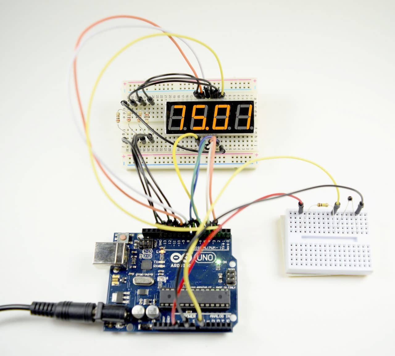
what is the name of that white pin board and through which i can install the code i to device
void clearData(){
while(data_count !=0){
Data[data_count–] = 0;
}
return;
}
I have not understood how this works?
If you mean the code as written with a single minus sign than it doesn’t. If you mean the original with two minus signs then read on.
Data is an array of chars and this code is meant to walk backwards through it and set each char to the null char, aka char(0). Based on the code this is neither necessary nor 100% correctly done.
Starting with the fact that it is unnecessary. Data is neither printed nor tested unless data_count is equal to 7 and therefore simply setting data_count back to 0 would suffice as all chars would be overwritten on next password entry. This however does leave the last typed password in memory which could be a security concern. It could also cause other unintended effects if the code was expanded upon. Thus clearing it is a better option.
Now for the intention of the code. It is meant to set all chars to the null char. However it does not do this. After entering the password, data_count equals 7 and thus on the first pass through the loop it sets character 7, aka the 8th character, aka the null terminator, to null which it already is. The loop then exits when data_count reaches zero but before setting Data[0] to 0 leaving the first character of the password in memory.
By changing the line Data[data_count–] = 0 from post-decrement to pre-decrement as in Data[–data_count] = 0 it would then correctly set the chars with indexes 0 – 6 to 0 and work as intended.
In that last line there should be two minus signs after the first data_count and then two minus signs before the second data_count but the forum changes that to only one apparently. I also notice the time of the post is GMT and not local time.
Fantastic, the best keypad tutorial i have found,
it was really helpful, thank you
Great website! I need to determine a temperature limit with a remote so the temperature sensor activates the relay. The DHT works fine but I can’t make the remote to do inputs for no reason. Can you help?
i am using the same code and it’s showing errors like”a:34: error: ‘LiquidCrystal_I2C’ does not name a type”,”a:32: error: ‘customKeypad’ does not name a type
customKeypad = Keypad(makeKeymap(hexaKeys), rowPins, colPins, ROWS, COLS);”.what does that means.
plz reply.
Hello,
my project is smart shopping cart. but i am confused about how setup keypad with this project because when i read rfid card on rfid reader and i want to buy multiple items so i want to do that when i read one product so in keypad i choose 2 so one time i read the product and i buy two items with keypad.
if you have any logic for this in code please let me know
thank you.
How do you stop the keypad from taking input so that if i press a key noyhing happens
Great tutorial
Im happy to use the keyad library but i wanted to understand as well and it was hard to find a tutorial that explained the process behind it and you’ve done that. Cheers.
Hi
What happens if you press 2 buttons in a same column simultaneously ?
Will they not short a HIGH and LOW output of the Arduino UNO?
Should there not be resistors in the row lines to avoid a short?
I suppose the columns are connected to 4 inputs with pullups and the rows to 4 outputs?
Is there an Arduino that can read a matrix of 75 switches, with one to 75 of them closed simultaneously, in any possible combination? Having all 75 closed would be a ‘unicorn’ event but since it’s *possible* the system must be able to handle it.
It will also need to be able to read a few more toggle and pushbutton switched not part of the matrix.
The goal is replacing a complicated 1-to-1 wiring setup operating a 5×15 array of lights with Neopixels while keeping the original switches. The large “hose” of wiring between will be replaced with something like an Ethernet cable to carry power and data to the refitted display.
Price is definitely a consideration. $300 for a special keyboard encoder capable of doing this is completely off the board.
How do I add a tact switch for password confirmation?
Here is a great DIY project to make a unique keypad using only 3 pins – It uses a shift register and by using their library SIKTEC_Keys u can easily attach functions to each key combination. Great stuff (https://www.amazon.com/dp/B09CLFTYN2)
Hi I have my arduino set up exactly like in the diagram. The LCD turns on but nothing happens when I hit the keypad. Any ideas? I am using the part called CODE FOR OUTPUT TO AN LCD
Hello, wondering if the password code can be adjusted to use multiple passcodes to do multiple actions if correct.