
In this tutorial, we will first take a look at how switches work and the types of switches that you can use for your projects. Then, we will see how to use these buttons and switches on the Raspberry Pi. Let’s get started!

How a Switch Works
Let’s just say that the idea behind the switch is the same as the analogy in a water tap. The flow of water is controlled by a water tap, or in the engineering world, a valve. When you open the tap, the water flows and when you close it, the water is restricted from flowing. The same thing is implied in the electronics world: think of the water as the current or the flow of electrons and the switch as the tap or valve to control the flow of current.
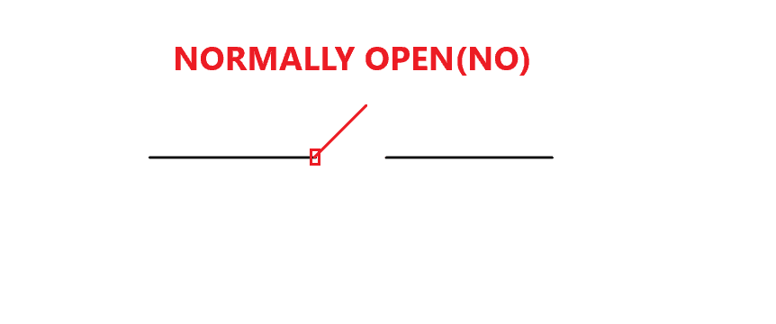
Most switches are in the normally open condition (NO), which means that the circuit connected with the switch is not linked with the power supply as the switch is open. Unless the switch is pressed, the circuit stays in that position.
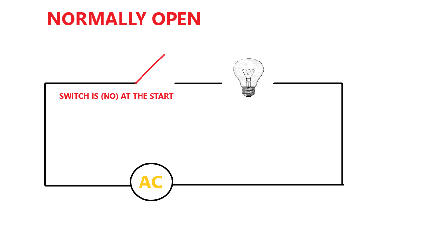
Let’s use a normally open switch in a circuit. Below is a bulb connected to the AC supply with a NO switch. The bulb will not light up until the switch is closed.
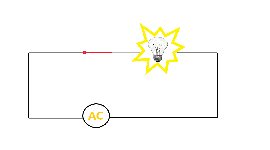
As the switch is pressed, the circuit gets completed and the bulb lights up.
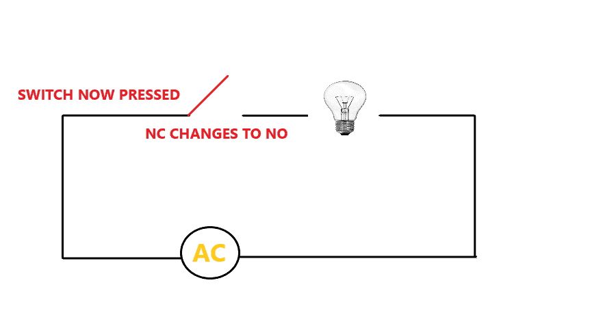
The other type is called the normally closed switch (NC) which works in the opposite manner. Though you might not see normally closed switch in electronics, you will see them in electrical applications like power control and process control systems.
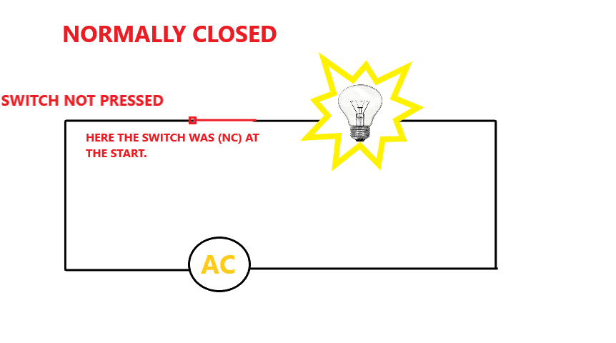
The circuit below shows a bulb connected to the AC supply with a normally closed switch. Notice here that the circuit is already closed, and the bulb is supplied with power from the AC mains. The switch is closed until it is pressed or used. When you push the button of this normally closed switch, the circuit will break, and no current will flow to the light bulb. A normally closed switch works opposite of normally open, and hence, it is used in many electrical applications in the industries by using contactors and relays.
The picture below shows the circuit after the button is pressed.
Poles and Throws
The most essential part of a switch are the poles and throws. In using a switch for your project, better to know first how many individual circuits you want your switch to control and if you want the switch to control more than one channel simultaneously. As such, you will need to understand the pole and throw of each type of switch.
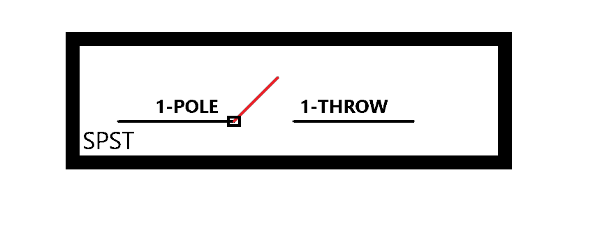
A “pole” basically means the number of circuits that can be attached and controlled with a switch. A single-pole switch can be used to turn on and off a single circuit, while a three-pole switch can control three circuits, and so on. Further, a “throw” means the number of points a pole can connect to the switch. For a more detailed discussion on this, check out our Complete Guide to Electronic Switches article.
Here is a schematic diagram of a single pole, single throw (SPST) switch:
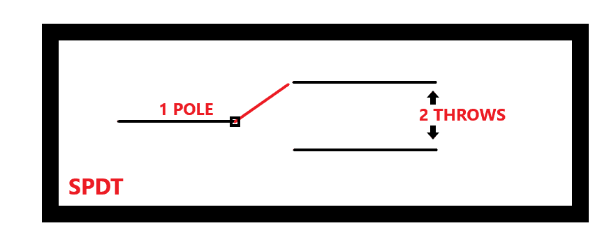
There are other switches as well like SPDT (single pole, double throw) and DPDT (double pole, double throw):
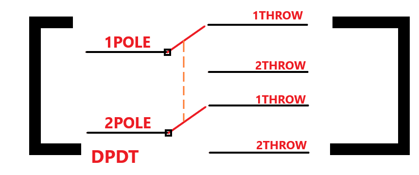
If you look closely at the DPDT switch, you can see an orange dotted line in between the poles. This line implies that when you press the switch or push the switch, both the poles change simultaneously with each other, changing from the first throw to the second throw at once.
Now that we have learned all the basics related to the switches, we will discuss the different switches we can use for our projects.
Types of Switches
There are three main types of switches:
- Mechanical – commonly used in homes as switches for your television, light bulbs, and fans.
- Electronic – commonly used in solid state circuits for switching devices with an electronic input signal.
- Integrated sensors – used when a device needs to be turned on and off depending on the reading of a sensor. These switches are integrated with sensors. For example, when a temperature sensor detects a rise in temperature, it will switch power to a fan and turn it on.
Mechanical Switches
Switches that require human intervention are called mechanical switches. In simple terms, a person must press, pull, push or release in order for the switch to work and turn on and off a particular circuit.
Different Types of Mechanical Switches:
Push Buttons
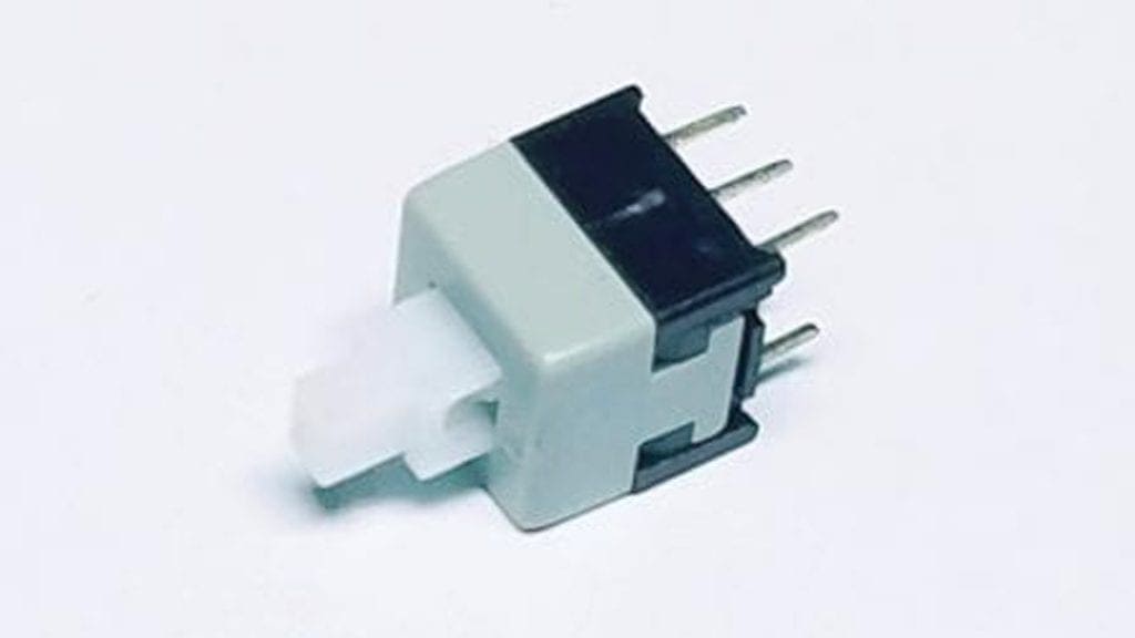
The standard form of switch used in electronics is a push-button switch. This push-button SPST switches are used to either make or break a circuit by a simple push action. They generally come in the normally open (NO) configuration.
Toggle Switches
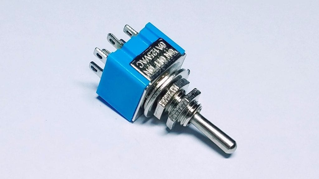
Toggle switches make or break a circuit by moving a lever up or down and comes in SPST, SPDT, and DPDT configurations. Some toggle switches have an off position in the center, and the circuit can be turned on by moving the lever in either the up or down direction.
Rotary Switches
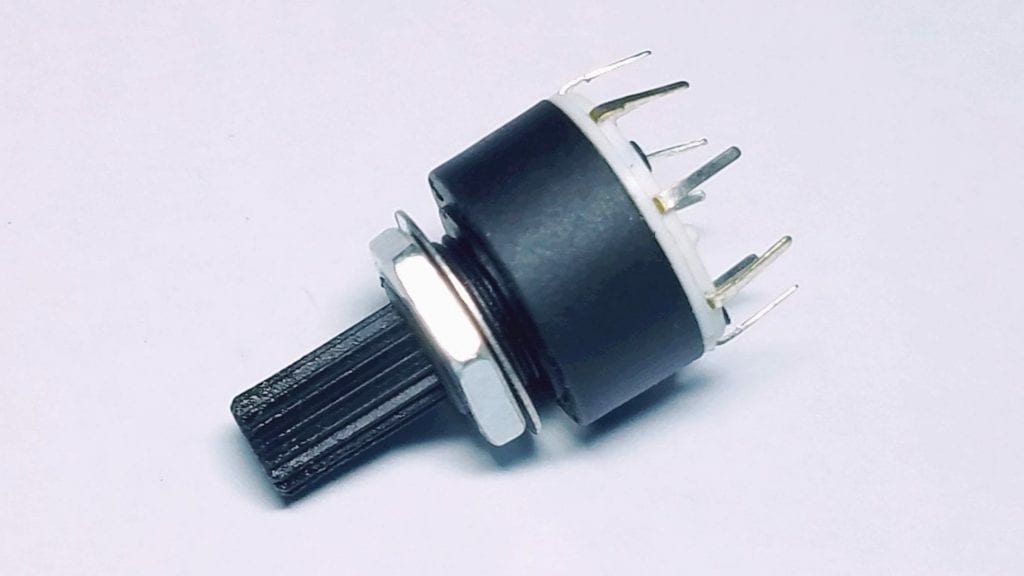
Rotary switches can switch multiple circuits on and off by rotating a knob. In general, you can switch up to 10 circuits with a single switch. Rotary switches are capable of handling large currents and voltages as well.
Slide Switches
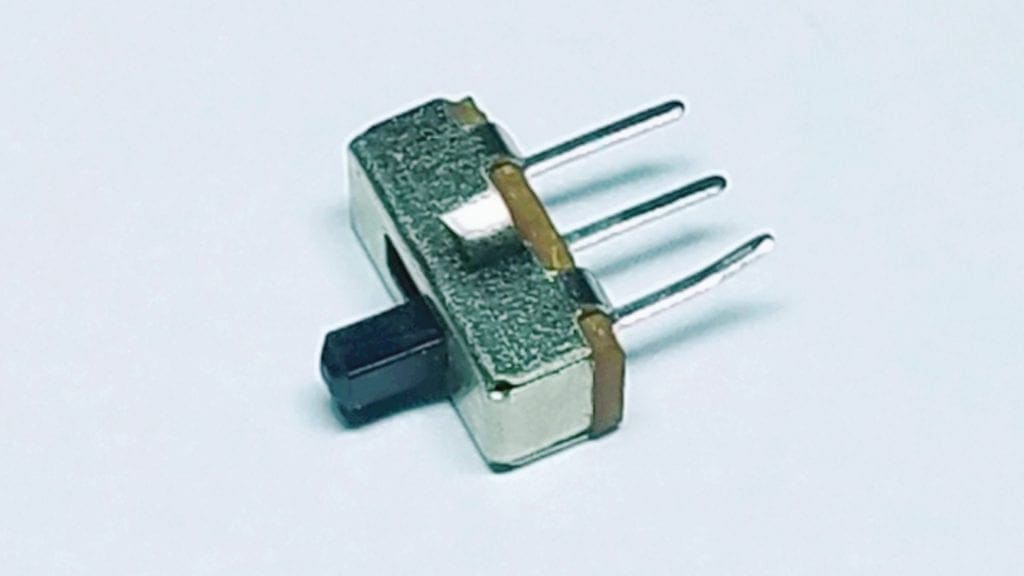
Slide switches turn on and off a circuit with a slider. In the initial condition, the slider is in a normally open state. After sliding the slider from one point to another, the circuit will connect with the power supply. The SPDT configuration is widely used in slide switches, but they also come in other configurations as well.
DIP Switches
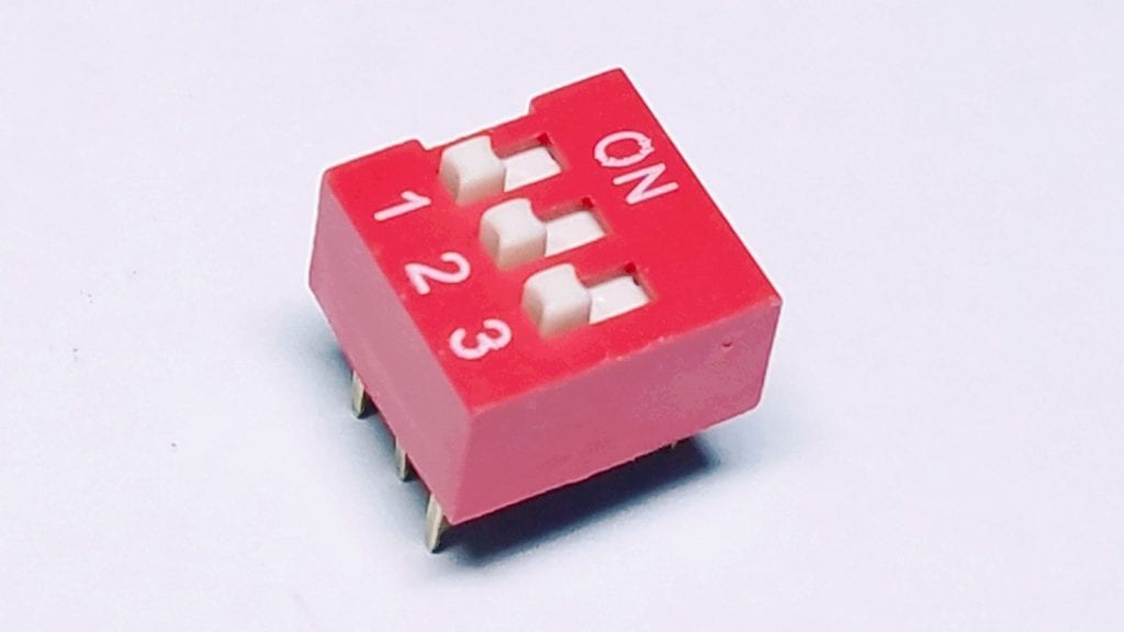
DIP switches contain multiple switches in a single package. They work more or less like slide switches, but their initial configuration is always SPST, and are used in low voltage and current applications.
Limit Switches
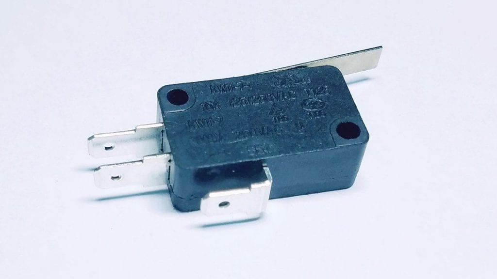
Limit switches are used in machines and industrial applications, where the movement of an object can retract the lever attached to the switch.
Electronic Switches
Electronic switches are made up of semiconductor material and require no human interaction to operate. A simple example of this switch is a transistor. If the base of the transistor has enough current, the circuit gets completed via the emitter and collector.
Different types of electronic switches:
- Bi-Polar Junction Transistors (BJT)
- Metal oxide semiconductor field-effect transistors (MOSFET)
- Insulated-gate bipolar transistors (IGBT)
Transistors are for switching small circuit applications as well as high-power circuits. It can change rapidly at a particular frequency and based on the transistor use.
Bi-Polar Junction Transistors
The bi-polar junction transistors (BJT) can work as a switch if they are biased in the saturation and the cut-off region. They are commonly known as current-controlled devices as the base is controlled via a specific amount of current.
Metal Oxide Semiconductor Field-Effect Transistors
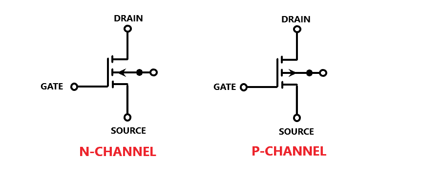
Metal oxide semiconductor field-effect transistors (MOSFET) are used as a switch as well as an amplifier for small signals in electronics. They are mostly used as amplifiers because of their infinite input impedance, which makes them capture almost every low signal without any problem. When using MOSFET as a switch, consider first its state that remains in between the cutoff and saturation region. MOSFET transistors are voltage-controlled devices.
Insulated-Gate Bipolar Transistors
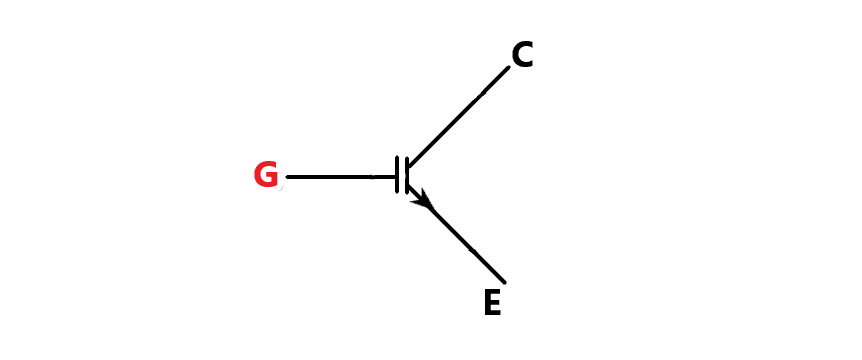
Insulated-gate bipolar transistors (IGBT) are used for fast switching. For this reason, it is usually used in switching amplifiers in audio amplifier circuits and also in industrial control systems. IGBT transistors have current and voltage ratings that are far higher than most MOSFETs. However, they have a lower switching speed compared to most MOSFETs.
Now let’s build an example project that can detect the on/off position of an SPST toggle switch to control an LED.
How to Use a Toggle Switch on the Raspberry Pi
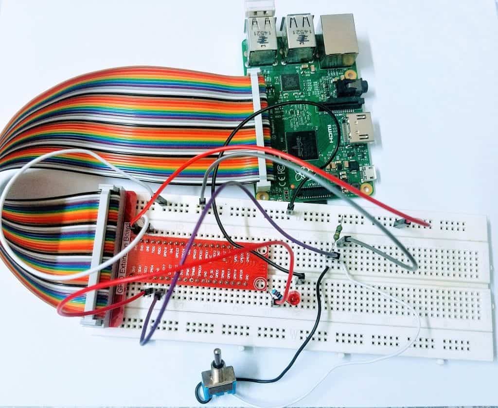
The most common type of switch you will see in most projects are toggle switches. They come in either SPST, SPDT, or DPDT type configurations. We will do a practical demonstration with a Raspberry Pi to light up an LED using the SPST toggle switch.
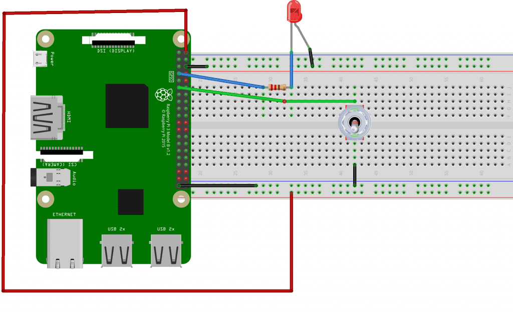
Components Required
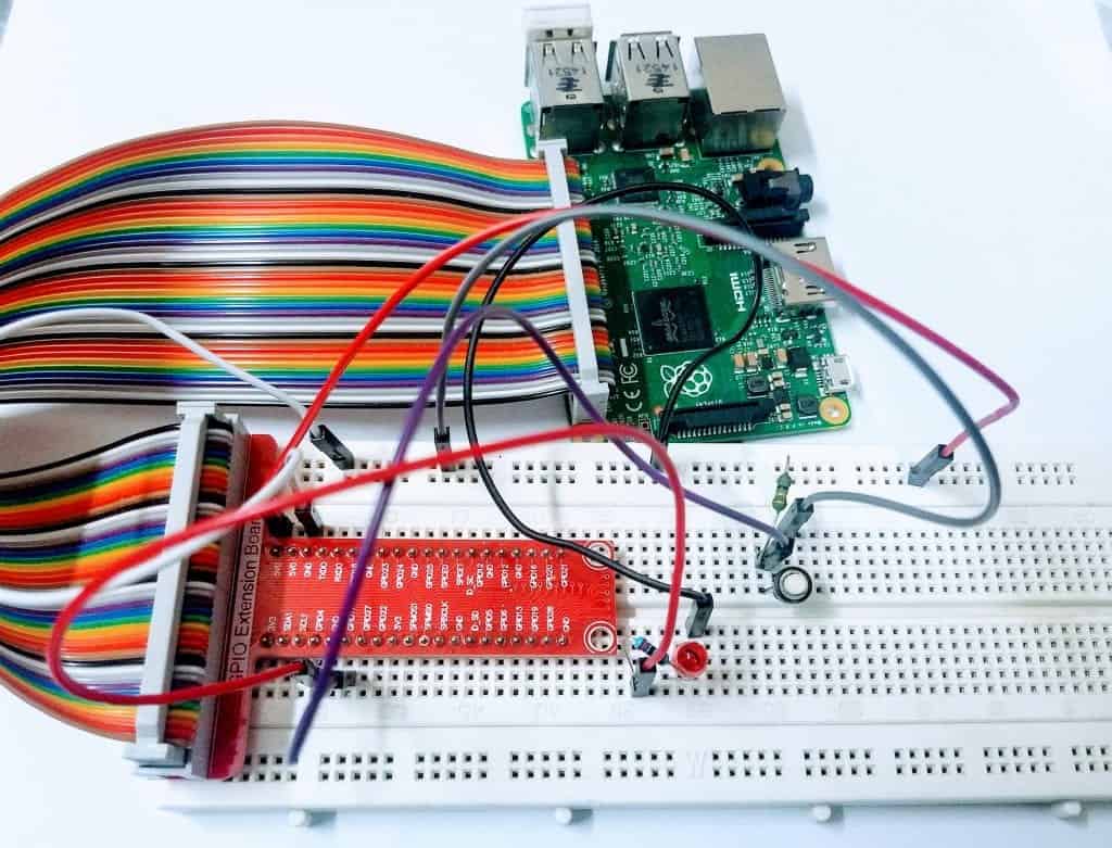
To start, connect the project as shown in the wiring diagram below. You can connect the LED and switch to other GPIO pins, just remember to change the pin numbers in the Python code.
The Code
The code below is a Python program. Copy the code and paste it into the Nano text editor. Then save the file as “LED.py”.
# import the libraries
import RPi.GPIO as GPIO
from time import sleep
GPIO.setmode(GPIO.BCM)

# set the pin numbers to be used from Broadcom chip

ledpin = 4 # assign a variable name to pin 4
pushpin = 17 # assign a variable name to pin 17
GPIO.setup(ledpin, GPIO.OUT) # set GPIO pin 4 as Output
GPIO.setup(pushpin, GPIO.IN) # set GPIO pin 17 as Input
GPIO.setup(4, GPIO.OUT, initial=GPIO.LOW) # set the initial output of pin 4 to be LOW

while True:
           GPIO.output(ledpin, not GPIO.input(pushpin)) # read the inverse value of input pin 17
           sleep(0.2)
To run the code above, enter sudo LED.py on the command line. Once the code is running, turn on the toggle switch and see what happens. You will notice a usual problem– the LED blinks erratically or not at all. This is because of the floating pins, a problem every microcontroller faces. To solve this issue, we need to use a pull-up resistor.
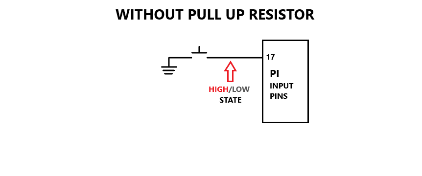
Floating Pins and Pull-Up Resistor
In general, whenever we try to connect a switch with boards like the Raspberry Pi, the switch will face continuous interference from the surrounding electromagnetic waves. These affect the pin as its state changes from HIGH to LOW or from LOW to HIGH. In some situations, the switch might not even work.
So, to solve this problem, we use a pull-up resistor. With this, we put the state of pin 17 at a stable state. This will only happen when the pull-up resistor turns putting the input state to HIGH while connected to the positive supply, grounded and until the switch is pressed.
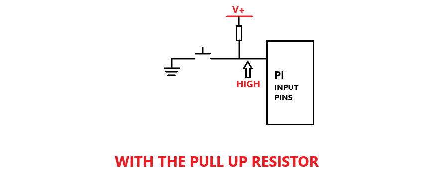
Notice how the resistor is connected with the toggle switch. On one end, it is attached to the positive supply, while the other is attached to a single wire with both the pin 17 and the toggle switch.
There are two ways you can use a pull-up resistor in this circuit. The first is by using the built-in pull-up resistor of the Raspberry Pi. Another way is by using an external pull-up resistor of 1k ohm for your circuit.
Code for Circuit with a Pull-Up Resistor
#Importing the Right libraries
import RPi.GPIO as GPIO
from time import sleep
GPIO.setmode(GPIO.BCM)

ledpin = 4
pushpin = 17
GPIO.setup(ledpin, GPIO.OUT)
GPIO.setup(pushpin, GPIO.IN, pull_up_down=GPIO.PUD_UP) # using the internal Pull up resistor
GPIO.setup(4, GPIO.OUT, initial=GPIO.LOW)

while True:
           GPIO.output(ledpin, not GPIO.input(pushpin))       # Reading the inverse value of input pin 17
           sleep(0.2)
Copy and paste the code above into a new file in Nano, then save the file with the name “LED.py.” You can name it whatever you want, but make sure to add the .py extension.
Now, run the code above by typing sudo LED.py into the command line. When you move the toggle switch, you should see that the LED turns on and off with each flick of the switch.
As mentioned above, another way to add a pull-up resistor is to use an external pull-up resistor in the circuit. The wiring diagram below shows how the external pull-up resistor is added to the previous circuit.
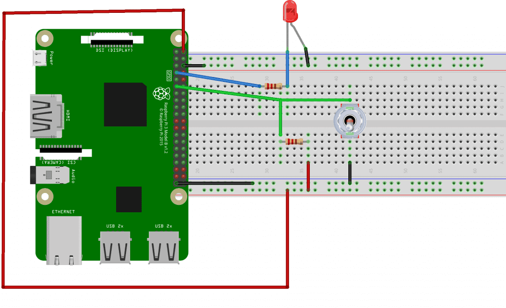
You can also use a pull-down resistor that works oppositely, but for now, we will only keep our focus on the pull-up resistor.
Now, let’s build another example project, but this time, using a tactile switch instead of a toggle switch.
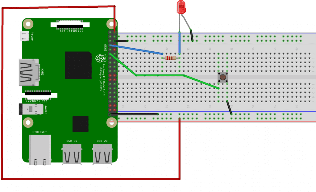
How to Use a Tactile Push Button on the Raspberry Pi
In this example project, we will use a tactile push button and a pull-up resistor to control an LED.
In this project, the LED will be ON by default. Pressing the push button will turn the LED OFF.
The Code
import RPi.GPIO as GPIO
from time import sleep
GPIO.setmode(GPIO.BCM)

ledpin = 4 # set output LED pin
pushpin = 17 # set input push button pin
GPIO.setup(ledpin, GPIO.OUT) # set ledpin as an output
GPIO.setup(pushpin, GPIO.IN, pull_up_down=GPIO.PUD_UP) # with pull up resistor

while True:
    GPIO.output(ledpin, GPIO.input(pushpin))
    sleep(0.2)
To run this on the Raspberry Pi, paste the code into Nano and save it with the file name “LED.py”. Then run it by entering sudo LED.py on the command line.
Notice that I am using the built-in pull-up resistor, not an external one, which makes things easier.
Remember to use the tips shared above especially when dealing with floating pins and pull-up resistors.
For any questions related to this topic, do leave a comment below and we’ll be happy to help!


Am I correct in thinking the circuit with the external pull-up resistor is not safe: I thought RasPi GPIO pins were NOT 5V tolerant. Shouldn’t the resistor be pulled up to 3v3 instead?
Could you publish the code needed to record when the switch opens and when it closes (changes state)? I’d like to record using a sail switch when my air conditioning unit is running. Using a sail switch will remove any chance of damage to the Pi or my A/C.
The switches will need debouncing. This ought to be mentioned with an example. Switches that are not debounced could cause a lot of problems.