Accelerometers can detect the magnitude and direction of acceleration. Many smartphones use accelerometers to detect when the phone is picked up or tapped. They can also be used to detect when a device is falling. Most laptops have internal accelerometers that switch off the hard drive before it hits the floor.

In this article, we will use an Arduino to get raw sensor data from an accelerometer and convert it into an acceleration value in g’s.
Watch the video for this tutorial here:
Introduction to the ADXL345 Accelerometer
The accelerometer we will use in this tutorial is the ADXL345 accelerometer from Adafruit:
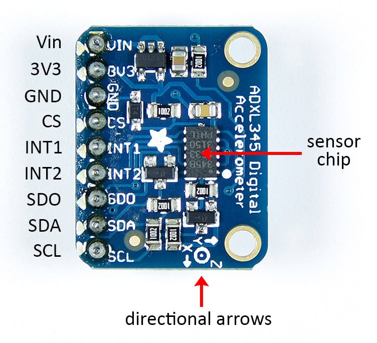
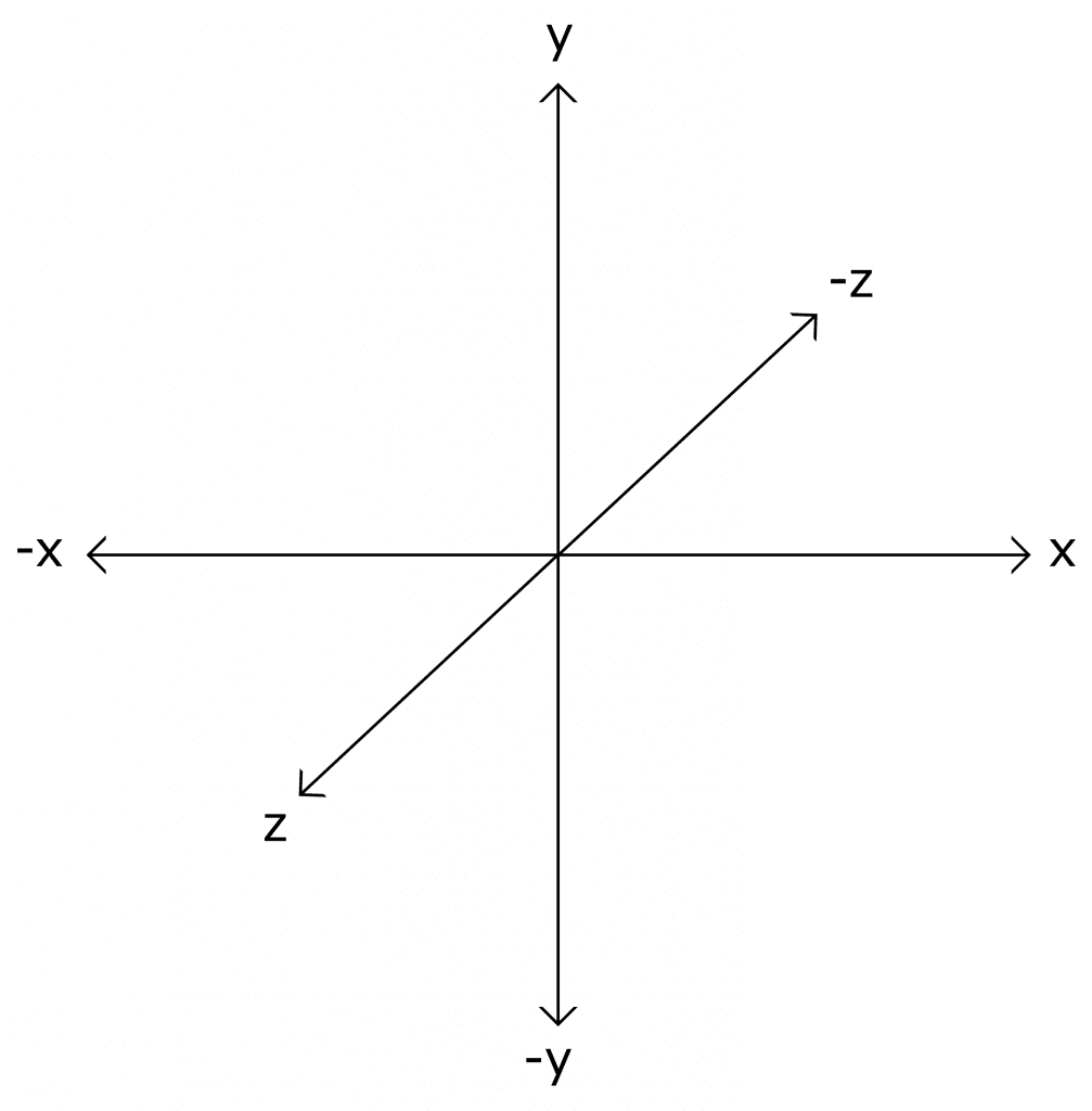
The directional arrows indicate the direction of each sensor axis (x, y, and z) in relation to the physical board. The z axis extends up and down, perpendicular to the x and y axes.
The ADXL345 can communicate with the Arduino over SPI and I2C. In this article we will use I2C, but SPI is an option if you want to use it.
ADXL345 accelerometer pins:
- Vin – Connects to a 5 volt power source.
- 3V3 – The ADXL345 can be powered with 3.3 volts or 5 volts. This pin is where the 3.3 volt power source would connect.
- GND – Connects to ground.
- CS – Chip select pin for SPI communication.
- INT1 – Hardware interrupt pin 1.
- INT2 – Hardware interrupt pin 2.
- SDO – Serial data output pin. Doubles as the MISO pin for SPI communication.
- SDA – SDA pin for I2C communication. Doubles as the MOSI pin for SPI communication.
- SCL – SCL pin for I2C communication. Doubles as the SCLK pin for SPI.
How the ADXL345 Accelerometer Works
Acceleration is the rate of increase or decrease of velocity:
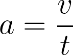
If you drive in a car and step on the gas, the car has a positive acceleration. If you step on the brakes, the car has a negative acceleration. This is known as dynamic acceleration.
Static acceleration is caused by forces like gravity. Accelerometers measure both static acceleration and dynamic acceleration.
Two common units of acceleration are meters per second squared (m/s2) and g’s. One g is defined as the rate of acceleration of gravity, which is 9.8 m/s2.
The ADXL345 outputs separate acceleration measurements for each axis, x, y, and z:
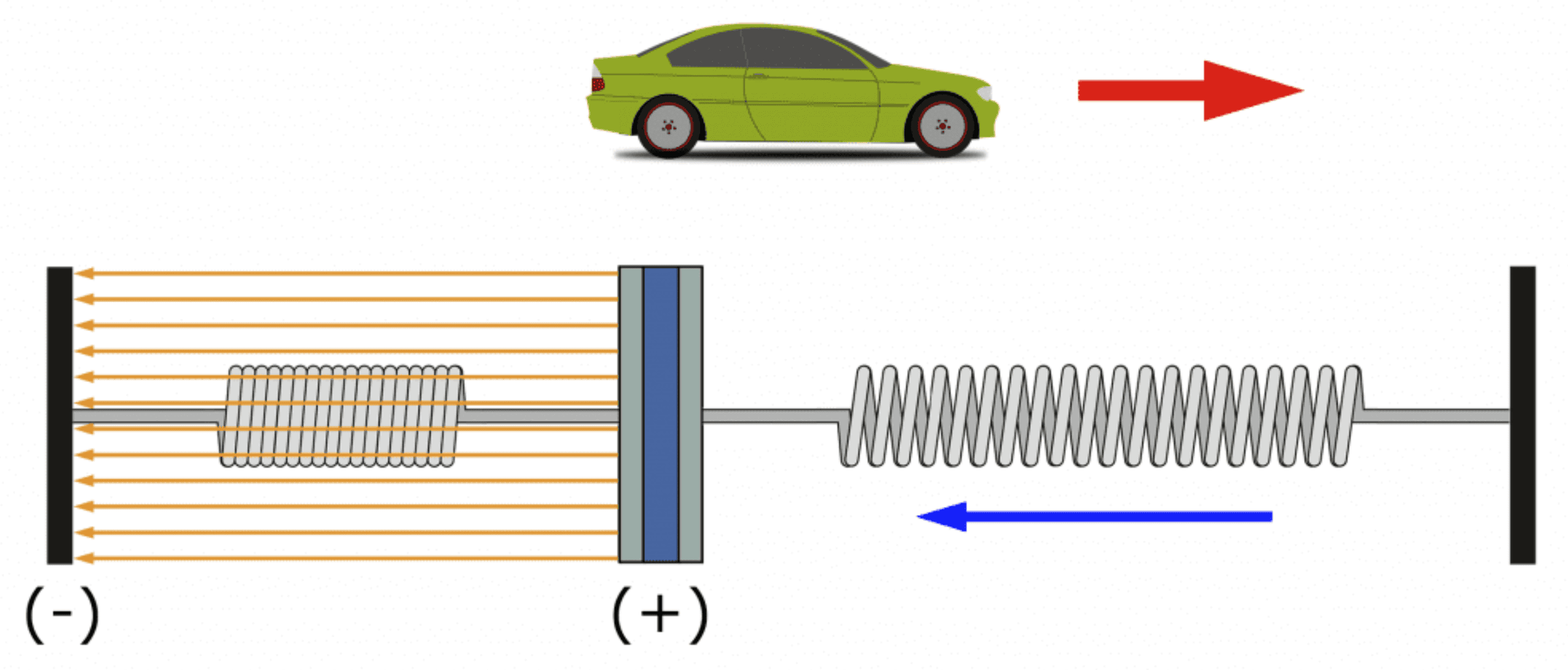
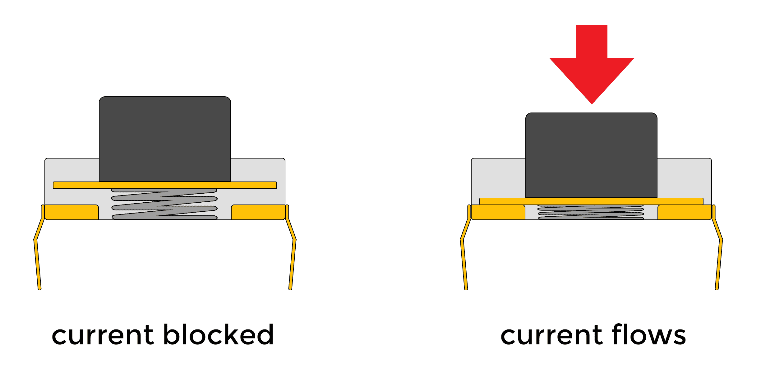
The ADXL345 measures acceleration by detecting changes in capacitance. Along each axis there is a tiny plate suspended between two micro-springs that can move back and forth:
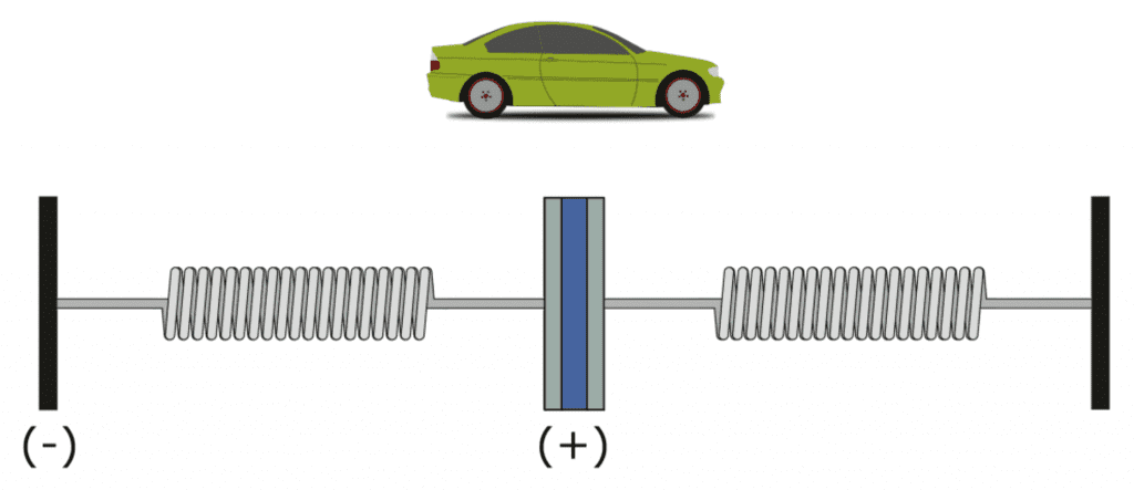
The mobile plate and the fixed plate are charged, so an electric field is formed between them:
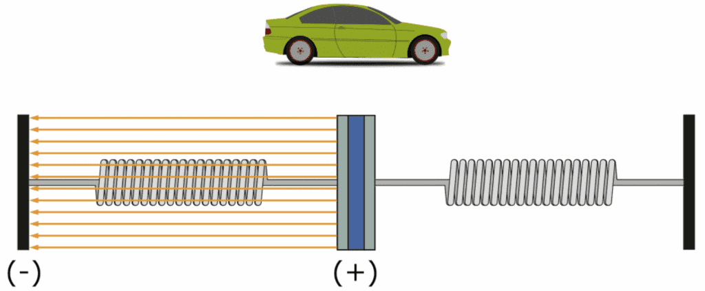
When the accelerometer is at rest, the electric field between the plates is constant. When the sensor accelerates, the mobile plate moves, and the distance between the plates changes.
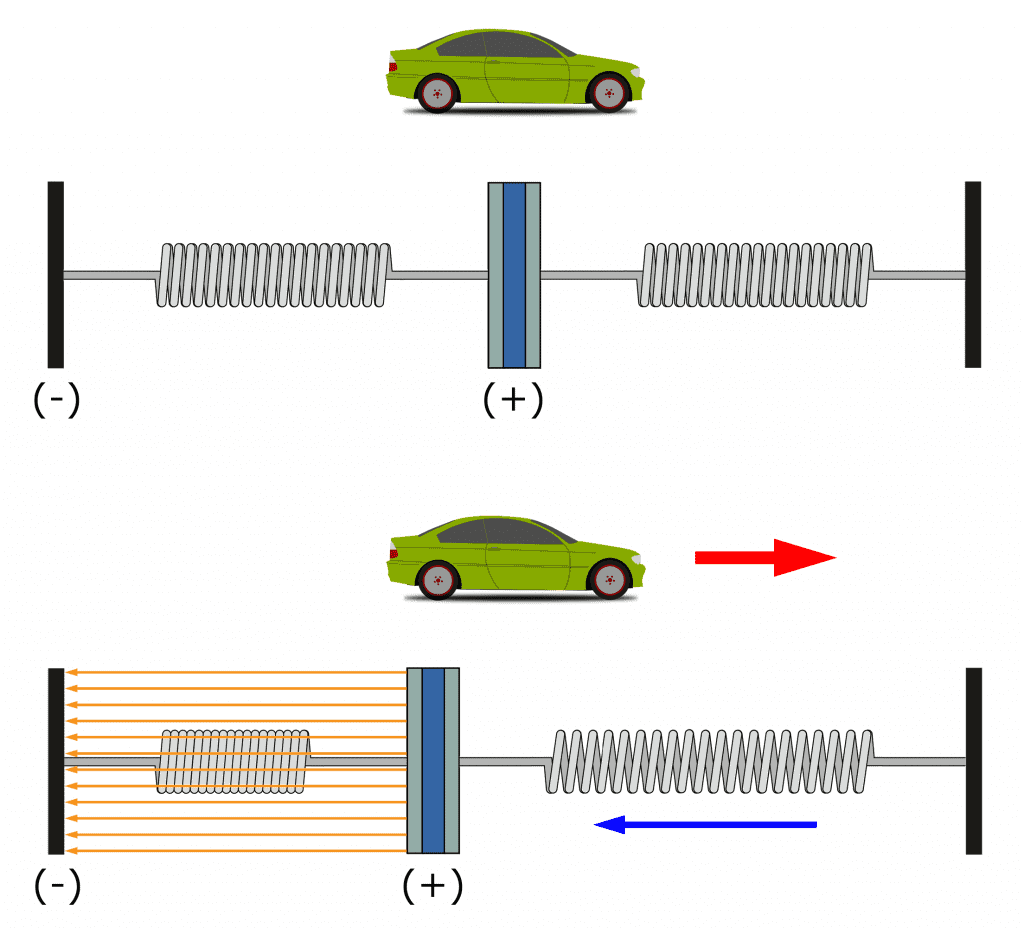
Capacitance is a function of the distance between two charged plates, so when the distance between the plates changes, the electric field between the plates also changes. The sensor measures this change in capacitance and calculates an acceleration value.
How to Connect the ADXL345 Accelerometer to the Arduino
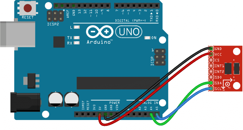
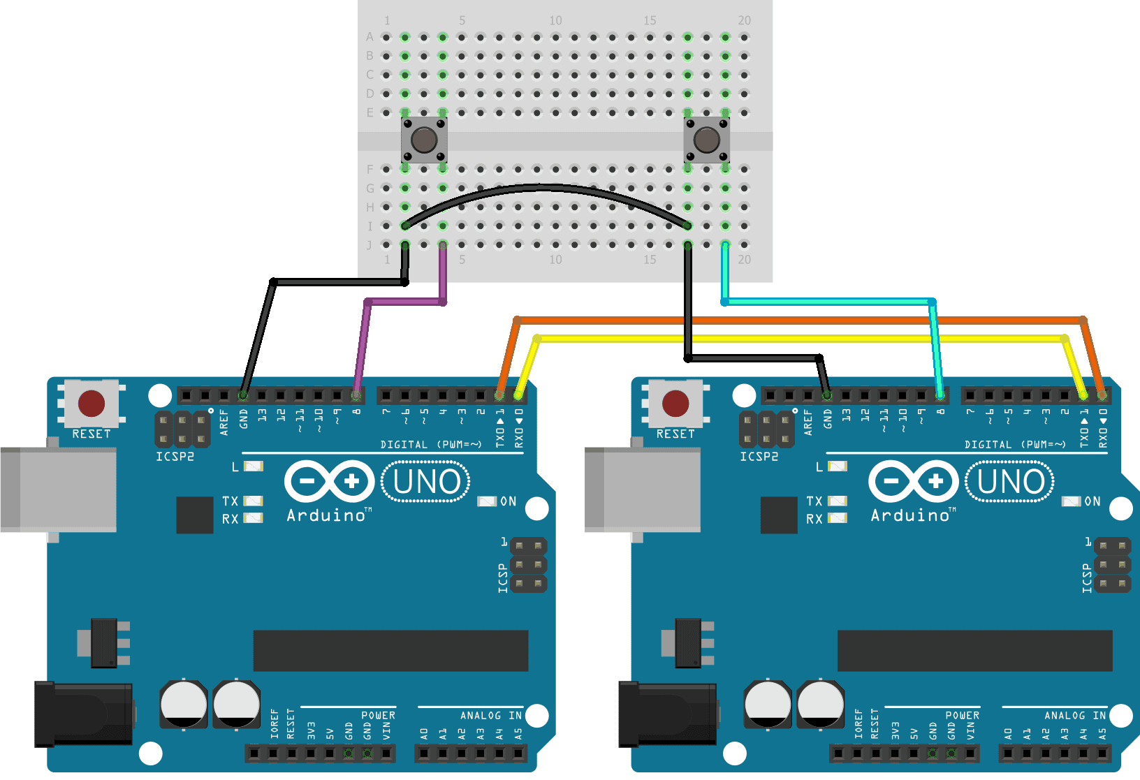
Let’s connect the accelerometer to the Arduino and take a look at the raw values it provides. We will connect the accelerometer with I2C, so the wiring is pretty simple.
These are the parts needed:
Connect the accelerometer to the Arduino like this:
How to Program the ADXL345 Accelerometer
To program the ADXL345 accelerometer we will use the Sparkfun ADXL345 library. Download and install the library here.
Once you get the library installed, upload the code below to the Arduino. The sketch will output the raw accelerometer readings to the serial monitor:
#include <SparkFun_ADXL345.h>

ADXL345 adxl = ADXL345();

int range = 2; // Range: 2g, 4g, 8g, 16g

void setup() {
  Serial.begin(9600);

  adxl.powerOn();
  adxl.setRangeSetting(range);
}

void loop() {
  int x, y, z;
  adxl.readAccel(&x, &y, &z);

  Serial.print("X: ");
  Serial.print(x);

  Serial.print("    Y: ");
  Serial.print(y);

  Serial.print("    Z: ");
  Serial.println(z);

  delay(250);
}
Explanation of the Code
The first thing we do is include the Sparkfun ADXL345 library. Next we create an object called adxl, which is a member of the ADXL345 class. We set the adxl object equal to the function ADXL345(). The ADXL345() function configures the communication mode that the sensor will use to talk to the Arduino. When there are no arguments passed to the function, as in this case, the sensor will use I2C to communicate with the Arduino. To use SPI, use ADXL345(10) instead.
Next we declare a variable called range, which will store the sensitivity range we want the ADXL345 to have. It can be either 2, 4, 8, or 16 g’s.
In the setup() section we initialize the serial monitor. Then we initialize the ADXL345 with the powerOn() function. This function is called through the adxl object we created earlier. Next, we call the setRangeSetting() function to set the sensitivity range of the sensor. We pass it the range variable, which stores the range setting we defined when we declared it.
In the loop() section, the first thing we do is declare variables to hold the sensor readings. The ADXL345 outputs separate acceleration measurements for each axis, so we need a unique variable for each axis. Therefore we declare three int variables – x, y, and z.
Next, we get the sensor readings from the accelerometer with the readAccel() function. The arguments of the readAccel() function are the variables that will hold the sensor readings from each axis. The sensor’s x axis measurement will be stored in the variable that is placed in the first parameter. The y axis measurements will be stored in the variable in the second parameter, and the z axis measurements will be stored in the variable placed in the third parameter.
Next we have a series of Serial.print() functions to print the values stored in the x, y, and z variables to the serial monitor. Then we delay for 250 milliseconds to slow down the output a bit.
Once you connect the ADXL345 to your Arduino and upload the code, open up the serial monitor. You should see values like this being printed out:
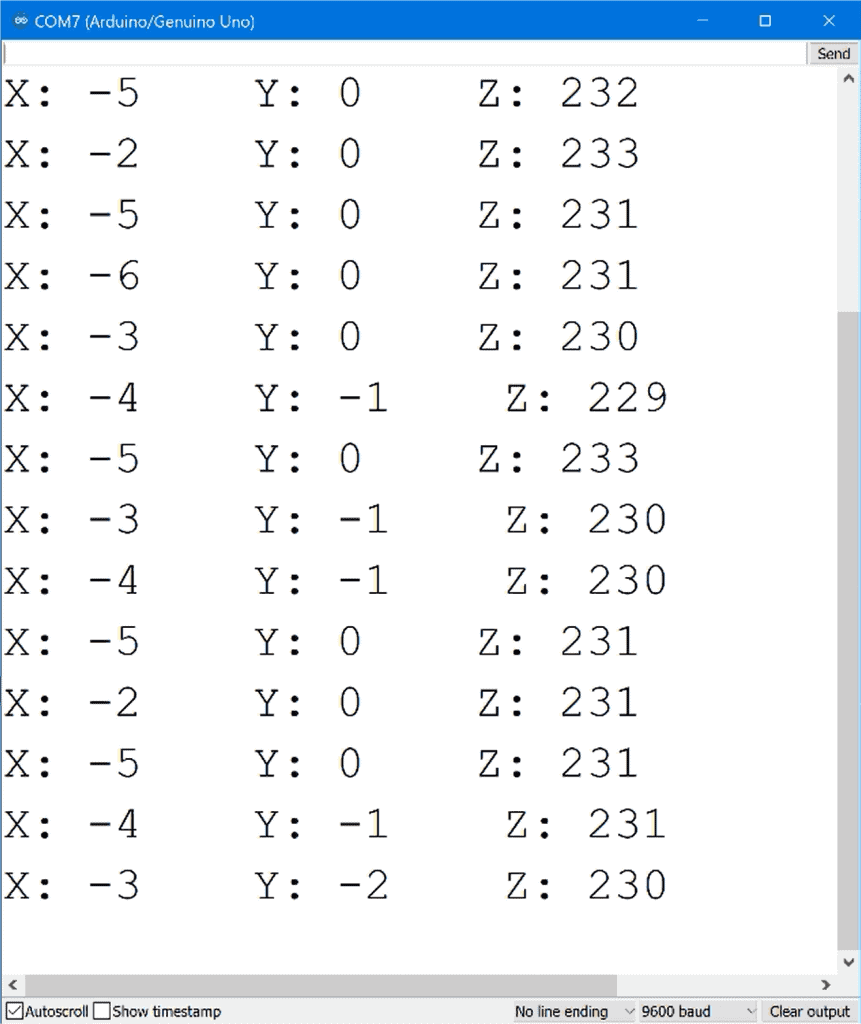
Notice how the X and Y values are close to zero, but the Z axis has a value around 230. The sensor was resting flat on a table when this screenshot was taken, so it wasn’t moving. But it was accelerating. The higher Z axis reading is caused by acceleration from gravity. Try moving the sensor around and see what happens to the values of the x, y, and z axes.
The raw values output by the accelerometer are not the typical Arduino ADC values between 0 and 1023. The numbers you see in the serial monitor are in “two’s complement” format. Two’s complement is a way to represent signed (positive and negative) numbers in binary.
We can convert the accelerometer’s two’s complement values to g’s with some conversion factors from the ADXL345 datasheet.
How to Convert Two’s Complement Values to G’s
In the specifications table on page 4 of the ADXL345 datasheet there is a section called sensitivity. This section has the scale factors for each sensitivity range::
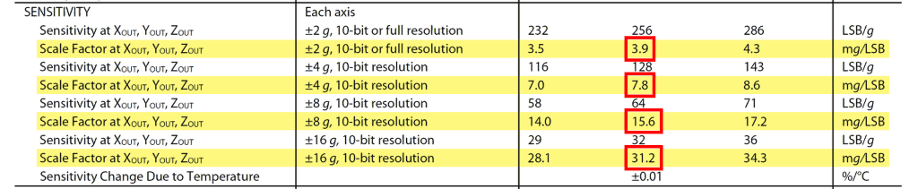
To get the acceleration readings in g’s, we need to multiply the sensor’s two’s complement output by one of these scale factors. Each sensitivity range has a different scale factor, indicated by the red box in the image above.
ADXL345 Accelerometer Output in G’s
Now let’s look at a sketch that will output the accelerometer readings in g’s. This sketch will actually output the sensor readings in milli g’s, but if you want the output in g’s, just divide the milli g’s reading by 1,000.
#include <SparkFun_ADXL345.h>

ADXL345 adxl = ADXL345();

int range = 2; // Range: 2g, 4g, 8g, 16g

void setup() {
  Serial.begin(9600);

  adxl.powerOn();
  adxl.setRangeSetting(range);
}

void loop() {

  int x, y, z;
  adxl.readAccel(&x, &y, &z);

  switch (range) {
    case 2:
      x = x * 3.9;
      y = y * 3.9;
      z = z * 3.9;
      break;
    case 4:
      x = x * 7.8;
      y = y * 7.8;
      z = z * 7.8;
      break;
    case 8:
      x = x * 15.6;
      y = y * 15.6;
      z = z * 15.6;
      break;
    case 16:
      x = x * 31.2;
      y = y * 31.2;
      z = z * 31.2;
      break;
    default:
      Serial.println("Please specify a range of 2, 4, 8, or 16 g");
  }

  Serial.print("X: ");
  Serial.print(x);

  Serial.print("    Y: ");
  Serial.print(y);

  Serial.print("    Z: ");
  Serial.println(z);

  delay(250);
}
Explanation of the Code
The top of the sketch and the setup() section are identical to the raw data sketch explained earlier.
In the loop() section, we declare x, y, and z variables to store the sensor readings from each axis. Then we get readings for each axis with the readAccel() function.
Next we convert the raw sensor readings to g’s by multiplying the raw sensor readings by the scale factor. The scale factor is different depending on which range setting we choose. This is a perfect application for a switch case statement. So we use a switch statement with the range variable as the condition. Each case statement will define what happens when the range is set to 2, 4, 8, or 16 g’s. When the range variable is equal to 2, the code in the first case statement will be executed. The scale factor for 2 g sensitivity is 3.9, so we multiply the output from each axis by 3.9. Then we have a break command so that the program exits the case statement.
Then we have case statements for all the other possible values of the range variable. When the range is set to 4 g’s, the scale factor is 7.8, so we multiply each axis output by 7.8. When the range is set to 8 g’s, the scale factor is 15.6, so we multiply all three axis variables by 15.6. And when the range is set to 16 g’s, the scale factor is 31.2, so we have to multiply everything by 31.2.
Then we have a default statement at the end of the switch case statement. The default statement will only be executed if the range variable was set equal to something different than 2, 4, 8, or 16. The code inside the default statement will print a line on the serial monitor that says: “Please specify a range of 2, 4, 8, or 16 g’s”.
Now we print the x, y, and z variables to the serial monitor with a series of Serial.print() functions. Finally we use a delay of 250 milliseconds to slow down the output to make it easier to read on the serial monitor.
After uploading the sketch, open up the serial monitor and you should see the acceleration readings being output in milli g’s:
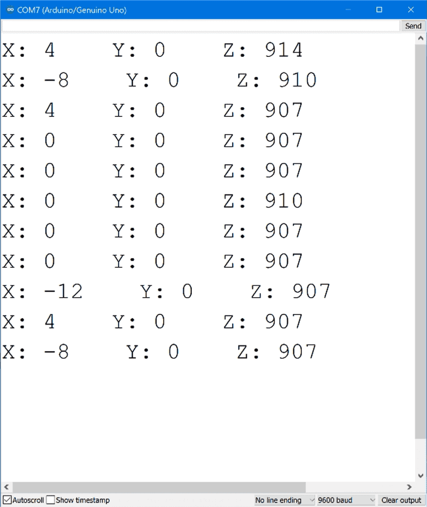
Notice that the Z axis values are around 910 milli g’s. That is pretty close to one g, which is the acceleration due to gravity.
Hope this article helps you setup the ADXL345 accelerometer on the Arduino! Just leave a comment below if you have questions about anything…

Thanks for a really great article that explains in a very understandable language! Since several of position defining sensors are used together, such as triple axis accelerometer, gyroscope, magnetometer and solid state compass to derive position, would it be possible to post an article such as this excellent one so we can tinker with Arduino with these sensors? Thank you so much again for this very enlightening article!
Your z values should use the third column of the table – i.e 4.3 for less than 2g. Your values will then be 992mG which is even closer to 1!