
Rotary encoders are useful for controlling servos and stepper motors, navigating menus on LCD displays, and also as speedometers that can measure how fast a wheel is rotating. In this article, we will look at how to set up a rotary encoder on the Arduino by building a simple program that counts up and down when you turn the knob.

Rotary encoders are used to measure angular rotation. They are similar in appearance to potentiometers but unlike potentiometers, rotary encoders can rotate around their axis without stopping. Also, while potentiometers output a resistance value, rotary encoders output a digital signal that can be used to determine the position of the knob.
Watch the video for this tutorial here:
Overview of a Rotary Encoder
Let’s take a closer look at a rotary encoder. The knob of a rotary encoder can rotate continuously around its axis without stopping. As you turn the knob, the rotary encoders has clicks, or “detents”. Each detent generates a digital signal that’s used by the Arduino to determine the position of the encoder knob. The number of detents per rotation defines the resolution of the encoder. Encoders with more detents have a greater resolution.
The Keyes KY-040 rotary encoder used in this article has 20 detents in a full rotation. This encoder also has a push button switch that can be controlled by pressing the knob down.
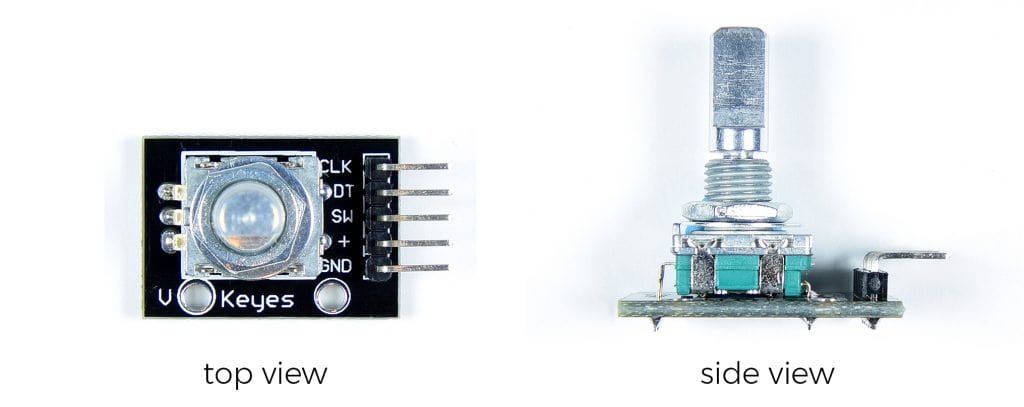
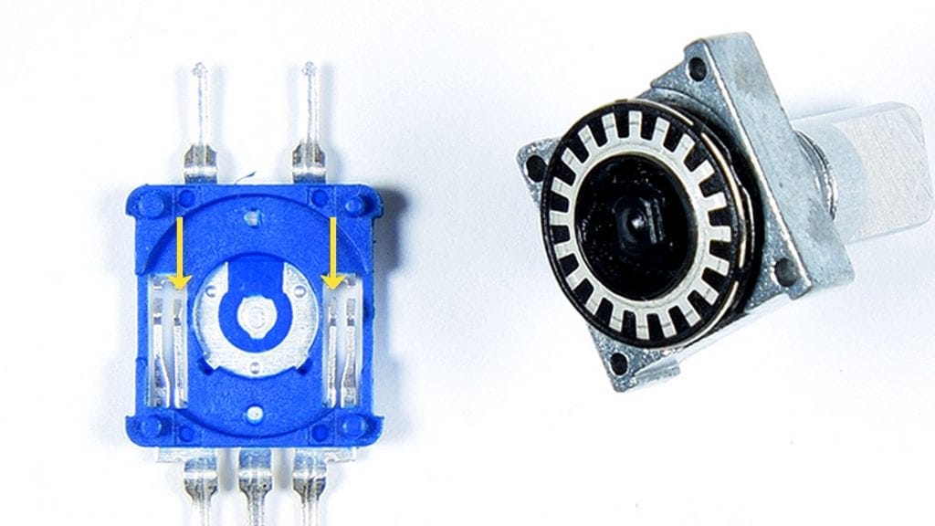
There are two types rotary encoders you’re likely to come across. One type is mounted to a PCB and has pins already attached like this one, the Keyes KY-040:
Another type is a stand alone version like this one:

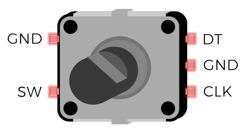
Stand alone rotary encoders have the same pins as PCB mounted rotary encoders, plus an extra ground pin:
How Rotary Encoders Work
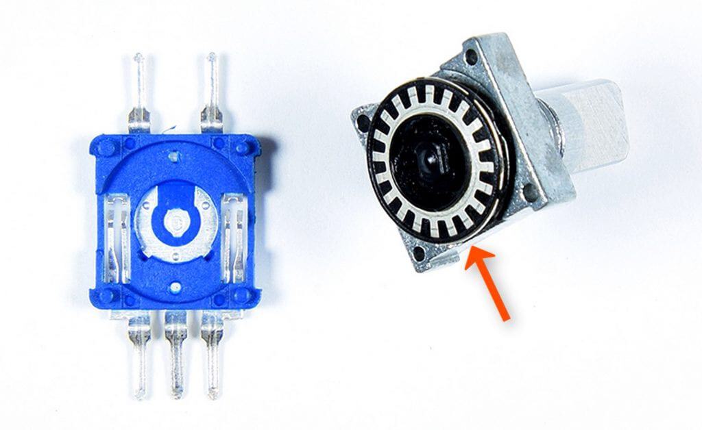
Inside the body of the rotary encoder is a metal ring that is attached to the knob and rotates with the knob. The metal ring has tabs on it, with each tab corresponding to one detent:
On the bottom half of the casing there are two sets of metal arms:
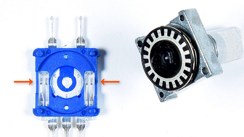
Both of the inner arms are connected to the ground pin:
The outer arm on this side is connected to the DT pin:

The outer arm on this side is connected to the CLK pin:

When the knob is turned the arms contact the metal tabs on the ring making a connection between the ground pin and the DT pin, or the ground pin and the CLK pin.
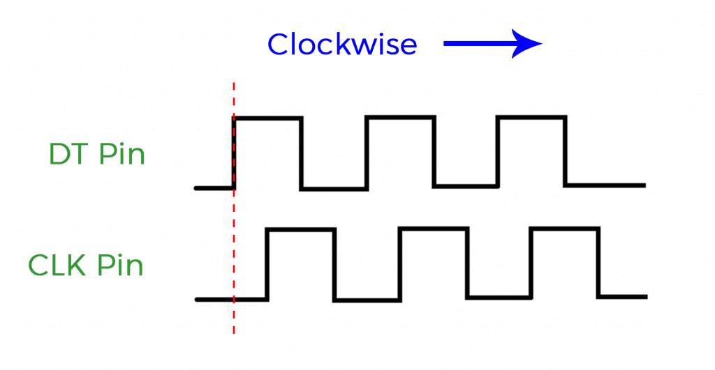
Let’s look at a waveform diagram to see how this works. When the encoder is rotating a square wave is output from both the DT pin and the CLK pin. When you turn the knob clockwise the DT pin goes HIGH first. At the same time the CLK pin is LOW:
When you turn the knob counter-clockwise the CLK pin goes HIGH first and the DT pin is LOW:
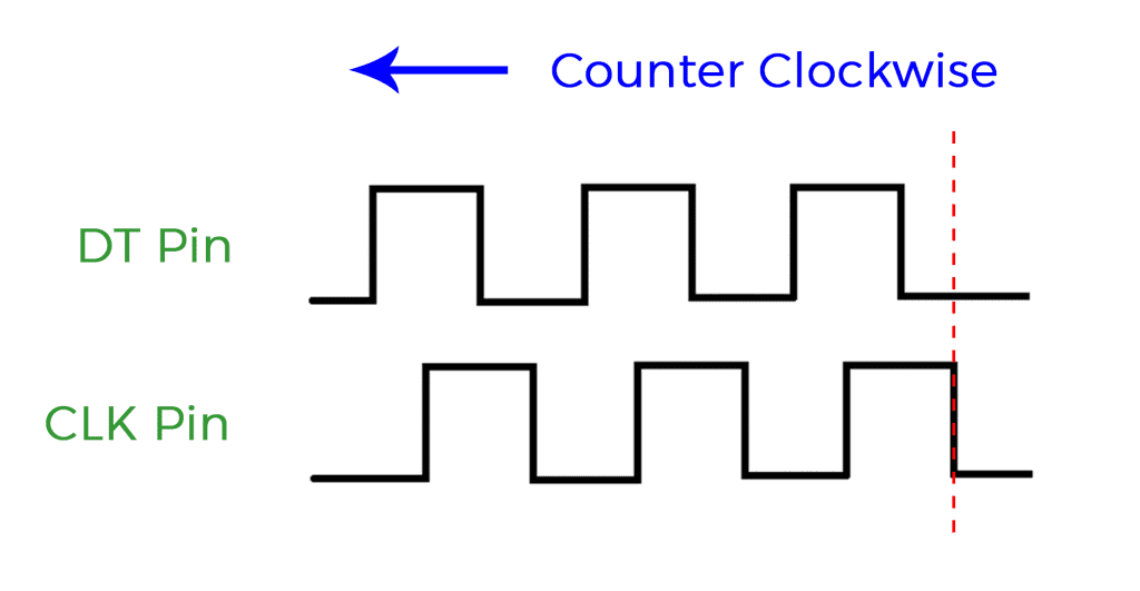
By detecting which pin goes HIGH while the other is LOW, we can determine which direction the knob is turning. Let’s see this in action by building a project that counts up when the knob is turned clockwise and counts down when the knob is turned counter clockwise.
How to Connect a Rotary Encoder to the Arduino
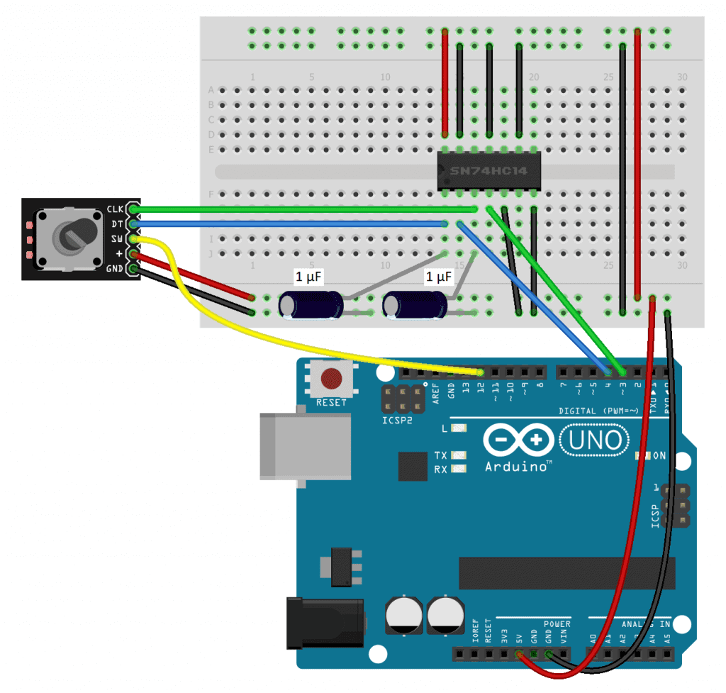
Like other mechanical switches, rotary encoders are prone to switch bouncing. Therefore, we will need to use a Schmitt trigger to de-bounce the signals from the rotary encoder. The Schmitt trigger we will use is the SN74HC14.
These are the parts you will need to build the project:
- Arduino Uno
- Jumper wires
- Breadboard
- SN74HC14N Schmitt trigger
- Keyes KY-040 rotary encoder
- Two 1 uF capacitors
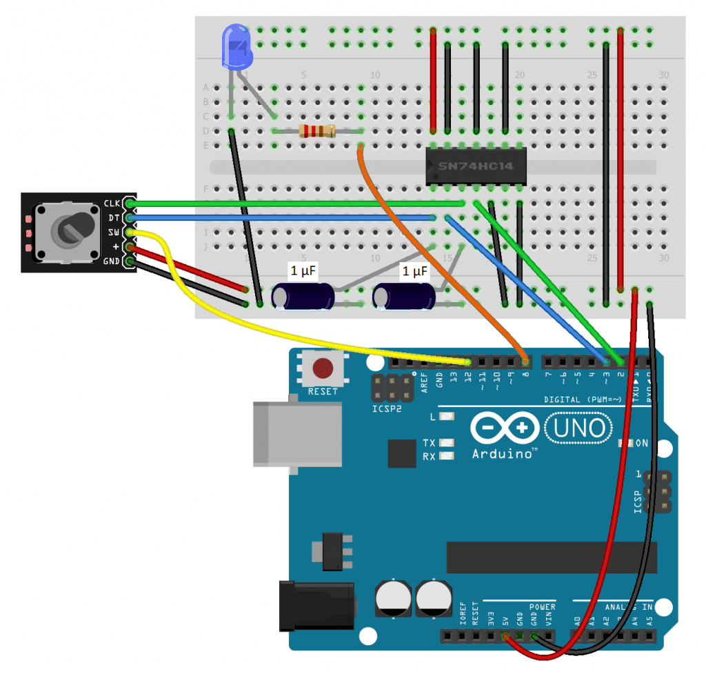
Follow this diagram to build the project:
How to Program a Rotary Encoder on the Arduino
Once the circuit is connected, upload this code to the Arduino:
int clkPin = 3;
int dtPin = 4;
int switchPin = 12;

int count = 0;
int clkPinLast = LOW;
int clkPinCurrent = LOW;


void setup() {
  pinMode(clkPin, INPUT);
  pinMode(dtPin, INPUT);
  pinMode(switchPin, INPUT_PULLUP);
  Serial.begin(9600);
}

void loop() {
  int switchState = digitalRead(switchPin);

  if (switchState == LOW) {
    count = 0;
  }

  clkPinCurrent = digitalRead(clkPin);

  if ((clkPinLast == LOW) && (clkPinCurrent == HIGH)) {
    if (digitalRead(dtPin) == HIGH) {
      count--;
    }
    else {
      count++;
    }

    Serial.println(count);
  }

  clkPinLast = clkPinCurrent;
}
Explanation of the Code
In the beginning of the sketch, we declare variables to store the readings from the CLK pin (clkPin), DT pin (dtPin), and SW pin (switchPin). Next we declare a variable called count to store the count number. The count will start at zero, so it’s initially set equal to zero. The clkPinLast variable keeps track of the last state of the CLK pin. It’s initially set equal to LOW. Then we declare another variable called clkPinCurrent that will store the current state of the CLK pin and set it equal to LOW as well.
In the setup() section, we use pin mode to set each pin as an INPUT. We don’t want the switchPin to float, so we use the internal pullup resistor. We will print the counts to the serial monitor so we initialize that too.
The first part of the loop() section is used to reset the count to zero when the rotary encoder switch is pressed. To do that, we first create a local variable called switchState, and set it equal to the digital read of the switchPin. The if statement on the next line sets count equal to zero when the switchPin goes LOW.
Now we take the clkPinCurrent variable and set it equal to the digital read from the clkPin. Then we have an if statement that says “if clkPinLast equals LOW, and clkPinCurrent equals HIGH” (the CLK pin went from LOW to HIGH since the last time around the loop), then enter the body of the first if statement and evaluate the nested if statement. The nested if statement asks whether or not the dtPin is HIGH. If it is HIGH, then we decrease the count variable by one. Both if statements will only be true if the knob is turning counter clockwise.
If the knob is not turning counter clockwise, then it must be turning clockwise. So we can use an else statement to increase the count variable by one if the above if statements are not true.
Next we print the value stored in count to the serial monitor. As a last step, we set the clkPinLast variable equal to the clkPinCurrent variable. That way, the program can tell if the state of the clkPin has changed in the next cycle through the loop.
After you build the circuit and upload the code, open up the serial monitor and rotate the encoder knob. The count should increase or decrease once for each click of the encoder.
Using Interrupts With Rotary Encoders
If you want to use the rotary encoder to control another device, the Arduino will need to balance taking reads from the encoder with sending signals to the other device. Unfortunately, the Arduino isn’t very good at doing multiple things at the same time.
For example, say you want to have an LED blinking on and off at the same time the encoder is counting up and down. Blinking an LED uses the delay() function, which causes the Arduino to stop what it’s doing for the duration of the delay. During that time it won’t be able to detect clicks from the rotary encoder.
Luckily there is a solution to this problem in the form of an interrupt service routine. By triggering an interrupt service routine with each signal from the rotary encoder, the Arduino can perform other tasks and only be interrupted when a signal from the rotary encoder is detected.
On the Arduino Uno, pins 2 and 3 are the only pins that are able to trigger an interrupt service routine.
Here are the parts you will need to build this:
- Arduino Uno
- Jumper wires
- Breadboard
- SN74HC14N Schmitt trigger
- Keyes KY-040 rotary encoder
- Two 1 uF capacitors
- One LED
- One 220 Ohm resistor
Follow the diagram below to connect the example circuit:
How to Program Interrupts With a Rotary Encoder
Once the circuit above is connected, upload this code to the Arduino:
volatile int clkPin = 2;
volatile int dtPin = 3;
int switchPin = 12;

volatile int count = 0;
volatile int clkPinLast = LOW;
volatile int clkPinCurrent = LOW;

int ledPin = 8;

void encoderInterrupt() {
  clkPinCurrent = digitalRead(clkPin);
  if ((clkPinLast == LOW) && (clkPinCurrent == HIGH)) {
    if (digitalRead(dtPin) == HIGH) {
      count--;
    }
    else {
      count++;
    }
    Serial.println(count);
  }
  clkPinLast = clkPinCurrent;
}

void setup() {
  pinMode(clkPin, INPUT);
  pinMode(dtPin, INPUT);
  pinMode(switchPin, INPUT_PULLUP);
  pinMode(ledPin, OUTPUT);
  attachInterrupt(digitalPinToInterrupt(2), encoderInterrupt, CHANGE);
  attachInterrupt(digitalPinToInterrupt(3), encoderInterrupt, CHANGE);
  Serial.begin(9600);
}

void loop() {
  int switchState = digitalRead(switchPin);

  if (switchState == LOW) {
    count = 0;
  }

  digitalWrite(ledPin, HIGH);
  delay(100);
  digitalWrite(ledPin, LOW);
  delay(100);
}
Explanation of the Code
This sketch is very similar to the sketch in the previous project, with a couple differences. Since now we need to trigger interrupt service routines, we have to connect the clkPin and dtPin to pins 2 and 3 instead of pins 3 and 4 as in the last sketch.
We also need to add interrupt service routines for the clkPin and dtPin. Before variables can be used in interrupt service routines, they need to be declared as volatile. In this sketch count, clkPinLast, and clkPinCurrent are used in the interrupt service routine so they are declared as volatile variables. We also need to declare a variable for the LED pin (ledPin).
Next we create the interrupt service routine with void encoderInterrupt(). The code that goes inside the interrupt is the same code from the loop() section in the previous example that reads the dtPin and clkPin and increments and decrements the counter.
In the setup() section, we set the pin modes for each pin. The clkPin, dtPin, and switchPin are set the same as in the last example. But this time we also have an LED, so the ledPin variable is set as an OUTPUT.
The interrupt service routine needs to be called in the setup() section. To call the interrupt service routine, use the attachInterrupt() function.
The attachInterrupt() function takes three parameters – the digital pin to interrupt, the name of the interrupt service routine, and the mode of the interrupt. Each interrupt needs it’s own attachInterrupt() function, so in this sketch there is one for pin 2 and one for pin 3.
After you build the circuit and upload the code, open up the serial monitor. The LED should be blinking on and off. Now when you turn the rotary encoder knob, the count on the serial monitor should go up and down without any missed clicks.
Leave a comment below if you have questions about anything!

I did some experimenting with a rotary encoder. Contact bounce is a big issue especially if you’re turning the knob slowly. I found an example that used a gray code table to disallow illegal encoder states which helped a lot.
https://forums.adafruit.com/viewtopic.php?f=57&t=117518
Hi Jim, thanks for the tip… In my testing I found that hardware circuits using a Schmitt trigger produced the best results, but I will look into your suggestion!