Troubleshooting is the process of isolating and identifying a fault in something so that it can be repaired. There are lots of variables to consider when troubleshooting a faulty electronic circuit. In this article we will look at the techniques I have developed to troubleshoot electronic circuits from over 50 years in the electronics industry.

Adopt a Troubleshooting Mindset
A wise old technician I worked with taught me to use my senses before I take out any tools:
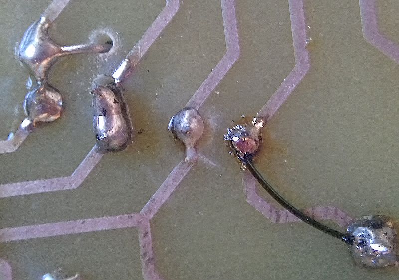
Look: Most problems can be found by just having a thorough look at the problem. This may include loose, missing, or misplaced components, burned components, solder splatter, loose bits of wire, and broken PCB traces.
Smell: Burned components have a nasty and characteristic smell and will often be discolored or outright carbonized. Also, the PCB under the component may be discolored.
Feel: Feel for any excessively hot components. Be careful not to burn your finger though. If anything is so hot it burns you, it is probably a problem.
Troubleshooting Tools
Continuity testers
A continuity tester (found on most multimeters) will allow you to check if there is a break or short in the circuit. Continuity testers apply a voltage across a pair of test probes and measure the current in the circuit. If no current is detected (indicating a short circuit), the continuity tester sounds an audible alarm.
Multimeters
A multimeter is used to measure voltage, resistance, and current. It’s good to have both a digital multimeter and an analog multimeter on hand, as they each have different applications.
Oscilloscopes
An oscilloscope is almost indispensable. Oscilloscopes let you to get high resolution look at the electronic signals flowing through your circuit.
Soldering tools
A soldering station or soldering iron is needed to repair solder joints and replace damaged components. A solder sucker or a solder wick can be used to remove the solder joints of faulty components.
Other tools
An X-Acto knife with sharp blades is useful for cutting wires and PCB traces.
To get more ideas on building up your electronics workshop, check out our article on How to Build an Electronics Work Bench.
How to Troubleshoot a Circuit
These are the things I check before diving deep into troubleshooting a circuit:
- Does the PCB or breadboard match the circuit diagram?
- Does the circuit have power?
- Is the circuit getting the correct voltage?
- Is the power supply connected the right way around?
- Are all ICs, transistors, and diodes the correct type?
- Are all resistors and capacitors the correct value?
- Are all polarized components (electrolytic capacitors, diodes, LEDs, etc.) connected the right way around?
- Do all of the solder joints have a good electrical connection?
- Are there any broken traces on the PCB?
Suspect any component that moves or has an interaction with a user. For example, components like potentiometers, switches, and push buttons can become fatigued at the solder joint to the PCB.
Motors have brushes and commutators that wear out.
Look for and test any fuses in the circuit. A fuse may look okay, but you can never be sure until you test it with a continuity tester.
Look for any cut, cracked, or burned PCB traces. Hold the PCB up to strong light to help identify these.
If the device is older than 30 years and has electrolytic capacitors, it is likely that they have dried out and become shorted. Replace them with equivalent values.
Older semiconductors (ICs, transistors, and diodes) are usually okay unless they have been stressed by lightning or overheating.
All of the above troubleshooting is purely visual, and you will often find the problem quickly. But if the circuit still does not work, it’s time to engage your main tools—logic and reason.
Advanced Troubleshooting
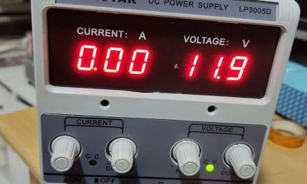
A good place to start is by powering the circuit with a bench power supply with a current limit control. Set the voltage to the right amount and set the current limit to 100mA. Power up the circuit. If the current goes up to 100mA and the voltage goes to zero, you have a short circuit.
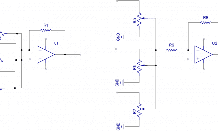
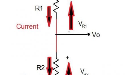
Next, check the transistors. Measure the voltage between the emitter and the base. The voltage should be close to 0.6V. The voltage between the collector and ground should be between half and full voltage if the transistor is off. The voltage should be close to zero if the transistor is on. If this is not the case, there could be a problem with the transistor.
Check the power supply. Measure the power supply output voltage with a multimeter to make sure it’s providing the correct voltage. Connect an oscilloscope to see if there are any hums, spikes, or glitches. Make sure there are adequate power supply decoupling capacitors for both high and low frequencies (0.1 uF and 100 uF capacitors).
If the circuit is digital, check that the logic levels are correct for the logic family in use. If the circuit has a CMOS chip, make sure all of the unused inputs are grounded.
If the circuit is still not working, it’s time to recheck if you understand how it was supposed to work, and if there could be some higher level design flaws.
If you have done all the above diligently and the circuit still won’t work, pack it away and come back tomorrow. Remarkably, this often works—taking a step back for a while gives your brain a chance to mull over the problem and think outside the box for a solution.
Often getting a new project to work will need patience and perseverance. Repairing previously working devices is more difficult, especially if the device has complex electronics and you cannot find a circuit diagram. But remember these two rules: suspect the power source first, then look, smell, and feel.
Hope this article has given you some ideas on how to troubleshoot circuits. Leave a comment below if you have any questions!


I have loved your explanations/posts. Any short specialized programmes.
I really liked the idea / techniques posted here. Thank you very much for this wonderful post!