Port expanders can be used to create extra GPIO pins on the Arduino. In this tutorial, we will learn how to use port expanders by building a project using the MPC23017 port expander to create two additional 8-bit ports and read and write to them using I2C on the Arduino. We will create some running lights and use bitwise actions to read input switches and display them on the serial monitor.

MPC23017 Port Expander
A port expander is like the extension cord (in the non-computer world) that allows more than one device to connect to a single port on a computer. However, there’s still a downside to it. For example, a 3Gbit/s port might have a hub or expander installed and now be able to accommodate 6 devices, but at a maximum of 3Gbit/s throughput bandwidth divided by the said 6 devices, or by however many are plugged in and being used.
The MPC23017 contains two 8-bit bi-directional ports which can be connected to the Arduino with an I2C interface. Its wire library takes care of the communication. And the chip has three selectable address lines so we can set it up with 23 = 8 possible addresses, or put additional MPC23017 chips on the same I2C line.
Bitwise Arduino Mini-Tutorial
If you have spent some time programming the Arduino, you may be very familiar with reading and writing to ports in a bit by bit manner, e.g. digitalWrite(12, HIGH). It’s easy to forget that they are actually 8-bit wide ports. In this project, we are confronted with two byte-wide ports that can only be written/read in a port-wide or byte-wide manner. By that, I mean you read all 8 bits at once and then have to single out the bit or pin you wanted. We will look at some seldom-used tools to do that.
Please note that & is very different from &&, as is|(OR) is different from ||. The symbols >> or << are not used to indicated greater or less than either; it is used to indicate a shift to the right or to the left. Another useful tool is to display bytes on the serial monitor in a binary fashion. For example, Serial.println(29, BIN); prints: 11101 (note: there are 3 zeros missing on the left-hand side). It would be nice if it showed us all of the 8 bits, but there is no simple Arduino function to do it. Alternatively, we can use a simple function illustrated below.
void loop() {
  printBin(29);
}

void printBin(byte inByte){
  for (int b = 7; b >= 0; b--)
    Serial.print(bitRead(inByte, b));  //now prints: 00011101
  Serial.println();
}
Let’s say we wanted to fetch a pin from port A but we are only interested in bit 2 (3rd bit from the right). Assume the byte contains 11110100.
We will use a “bit mask”. This is a byte of 0’s but a 1 in the position where we want to extract a single bit. If you AND a bit with 0, the result will always be 0 because 1 AND 0 is 0. Bitwise AND is & NOT && which is logic AND. The Serial.println(B11110100 & B00000100) will result to 00000100 which is 4 because 0100 is 4 DEC. To get our bit as HIGH or LOW, we use: Serial.println((B11110100 & B00000100) >> 2). This has used the mask to screen out the junk as before, and shift to the right by 2 places to get the result as a 1 or 0.
Actually there is an easier way. Remember that bits are numbered 0 to 7. Refer to the code below:
byte mybyte = B11110100;
Serial.println(bitRead(mybyte, 2));    // prints 1
Serial.println(bitWrite(mybyte, 3, HIGH), BIN); // prints  11111100
Serial.println(bitClear(mybyte, 3), BIN);  // prints  11110100
Wiring Up the Project
In this example project we will use the MCP23017 port expander to control eight LEDs depending on the input from an eight channel DIP switch.
These are the parts you will need to build this project:
- Arduino Uno
- MPC23017 port expander
- Eight position DIP switch
- Eight LEDs
- Eight 680 Ohm resistors
- Eight 10K Ohm resistors
- One 2.2K Ohm resistor
- Jumper wires
- Breadboard
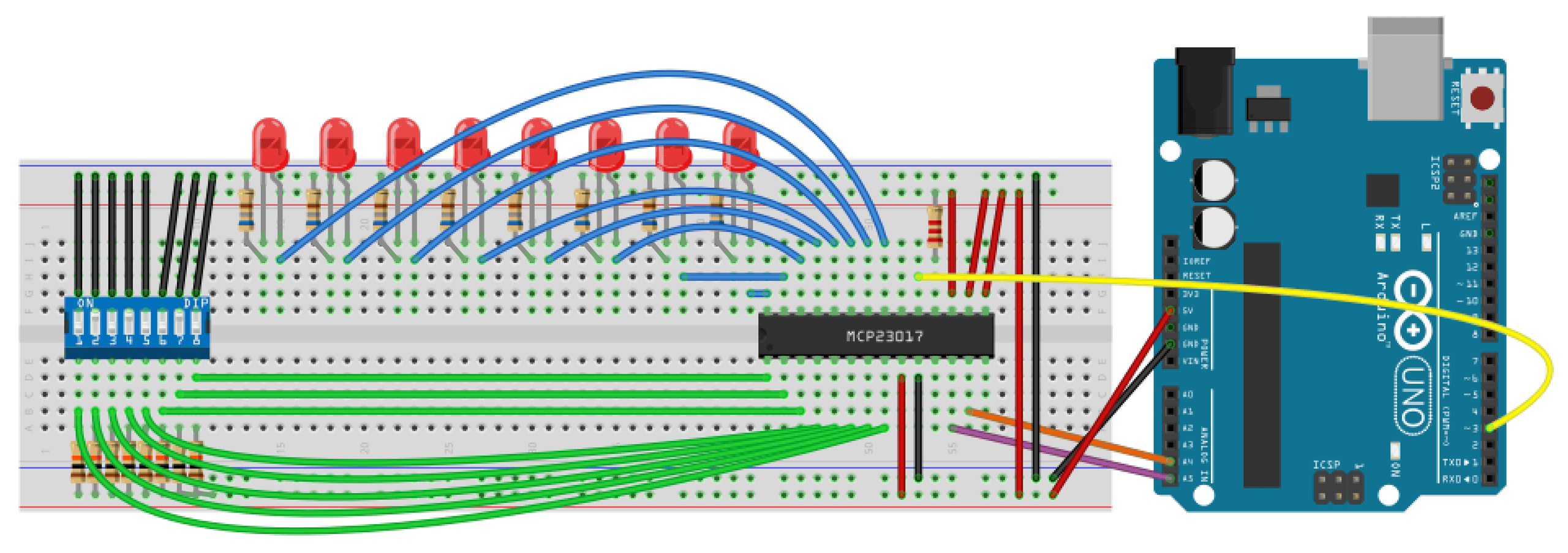
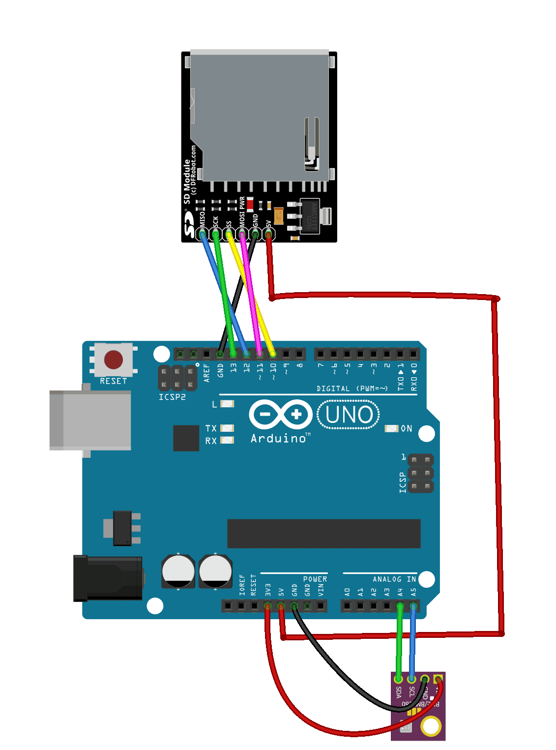
Follow the wiring diagram below to build the project:

The values of the current limiting resistors connected to the LEDs are 680 Ohms. The resistor connected to pin 18 of the MCP23017 is 2.2K Ohms, and the pull-up resistors connected to the DIP switch are 10K Ohms.
If you want to learn more about the Arduino, check out our Ultimate Guide to the Arduino video course. You’ll learn basic to advanced Arduino programming and circuit building techniques that will prepare you to build any project.
Arduino Code
Once everything is connected, upload this code to the Arduino. This program will output the bit value created by the DIP switch in raw and decimal format:
//simple read and write to MCP23017 port expander
#include <Wire.h>
byte byteVal=0;
byte chipAddr = 0x27;
byte GPIOA = 0x12; // PortA reg addr
byte GPIOB = 0x13; // PortB reg addr
byte IODIRA = 0x00; // PortA direction reg addr
byte IODIRB = 0x01; // PortB direction reg addr
void setup(){
Serial.begin(9600);
Wire.begin();
Wire.beginTransmission(chipAddr);
Wire.write(IODIRA); // IODIRA dir register
Wire.write(0x00); // set entire PORT A as output
Wire.endTransmission();
Wire.beginTransmission(chipAddr);
Wire.write(IODIRB); // IODIRB dir register
Wire.write(0xff); // set entire PORT B as input
Wire.endTransmission();
}
void loop(){
Wire.beginTransmission(chipAddr);
Wire.write(GPIOB); // read the inputs off PORT B
Wire.requestFrom(chipAddr, 1); // ask for 1 byte
byteVal = Wire.read(); // read it
Wire.endTransmission();
// write that input to PORT A
Wire.beginTransmission(chipAddr);
Wire.write(GPIOA); // address PORT A
Wire.write(byteVal); // PORT A
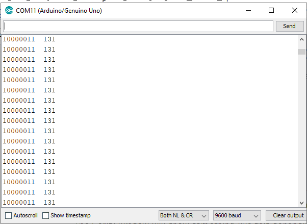
Serial.print(byteVal,BIN); Serial.print(" "); Serial.println(byteVal, DEC);
Wire.endTransmission();
delay (200);
}Explanation of the Code
In the first section, we include the wire library, then we declare the chip address, and then the port A and B data registers followed by the direction registers. This is similar to setting pinMode() in the normal manner.
In setup(), we make port A an output port, and port B an input port. It is worth mentioning that you don’t have to make the whole port output or input. For example, byte IODIRA = B0101010101 would make alternate input and output pins. In the loop() section we just read off port B and copy it to port A.
The serial window will show something like this, depending on the position of your input switches:
Code for LED Running Lights
Upload the code below to make the LEDs turn on, one after the other. Here we are using left shift << to move a bit to the left, causing the LEDs to move:
#include <Wire.h> // Wire.h
byte inByte=1;
byte chipAddr = 0x27;
byte GPIOA = 0x12; // PortA reg addr
byte GPIOB = 0x13; // PortB reg addr
byte IODIRA = 0x00; // PortA direction reg addr
byte IODIRB = 0x01; // PortB direction reg addr
byte i = 1;

void setup(){
  Serial.begin(9600);
  Wire.begin();

  Wire.beginTransmission(chipAddr);
  Wire.write(IODIRA); // IODIRA dir register
  Wire.write(0x00); // set entire PORT A  as output
  Wire.endTransmission();

  Wire.beginTransmission(chipAddr);
  Wire.write(IODIRB); // IODIRB dir register
  Wire.write(0xff); // set entire PORT B as input
  Wire.endTransmission();
}

void loop(){
  i=i<<1;
  if(i==0)
      i=1;
  Wire.beginTransmission(chipAddr);
  Wire.write(GPIOA); // address PORT A
  Wire.write(i);    // PORT A
  delay (500);
  Wire.endTransmission();
  Serial.println(i);
}Output on the Serial Window

Hope you enjoyed this tutorial on how to expand the Arduino’s GPIO pins with a MCP23017 port expander! Be sure to let us know in the comments below if you have any questions.

With a 5V to 3V3 level changer, this would also work on a Raspberry Pi. One could keep C but changing to Python 3.x is no problem
Hi, the second table is the same as the first. I assume this should light the LEDs in sequence in steps?