Keeping track of the date and time on an Arduino is very useful for recording and logging sensor data. For example, you could build an Arduino weather station that attaches a date and time to each sensor measurement. Another example is for an Arduino digital clock or calendar. Arduino-based clocks use the current time as a timer to remind or execute a scheduled command via the Arduino’s I/O pins.

In this tutorial, we will discuss the purposes of getting the current date and time on the Arduino, what are the different ways to get the current date/time, what is an Arduino Ethernet shield, and how to get the current time from an NTP server using an Arduino Uno with Ethernet shield.
How to Get the Correct Date and Time
There are several ways to get the current date and time. We can get it from a Real-Time Clock (RTC), a GPS device, or a time server.
- Real-Time Clock (RTC) – An RTC is an IC that keeps track of the current date and time data. It has its own battery source to keep the RTC running even if the main power source is off. Computers have built-in RTC devices.
- Global Positioning Device (GPS) – A GPS device communicates with satellites to determine its location anywhere in the world. Its GPS data also contains time data.
- Time Server – A Time Server is a computer on a network that reads the time from some reference clock and distributes it to the network. The clock source of a time server can be another time server, an atomic clock, or a radio clock.
In this tutorial, we will communicate with an internet time server to get the current time.
Network Time Protocol
The most widely used protocol for communicating with time servers is the Network Time Protocol (NTP). NTP is a networking protocol used to synchronize time between computers in a data network. Time servers using NTP are called NTP servers.
NTP Stratum Model
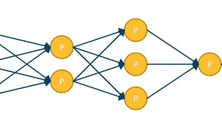
The NTP Stratum Model represents the interconnection of NTP servers in a hierarchical order. Not all NTP servers are directly connected to a reference clock. Some NTP servers are connected to other NTP servers that are directly connected to a reference clock or to another NTP server. See Figure 1.
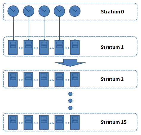
The NTP Stratum Model starts with Stratum 0 until Stratum 15. Stratum 0, a.k.a. reference clocks are high-precision timekeeping sources like atomic clocks, GPS sources, or radio clocks. Stratum 1 NTP servers connect to a reference clock or to other servers in the same stratum to get the time. On the other hand, Stratum 2 NTP servers connect to one or more Stratum 1 servers or to other servers in the same stratum to get the current time. This way of getting time between NTP servers go on until Stratum 15. There is also a Stratum 16 to indicate that the device is unsynchronized.
Communication via NTP
NTP communication is based on a Client/Server model. An NTP client initiates a communication with an NTP server by sending a request packet. A basic NTP request packet is 48 bytes long. The NTP server then adds its own timestamp to the request packet and sends it back to the client. This timestamp is the number of seconds since the NTP epoch (01 January 1900). To get the UTC time, we subtract the seconds elapsed since the NTP epoch from the timestamp in the packet received.
Getting the Current Date and Time on the Arduino
For this example project, we will use an Arduino Uno and an Ethernet shield to request time data from an NTP server and display it on the serial monitor.
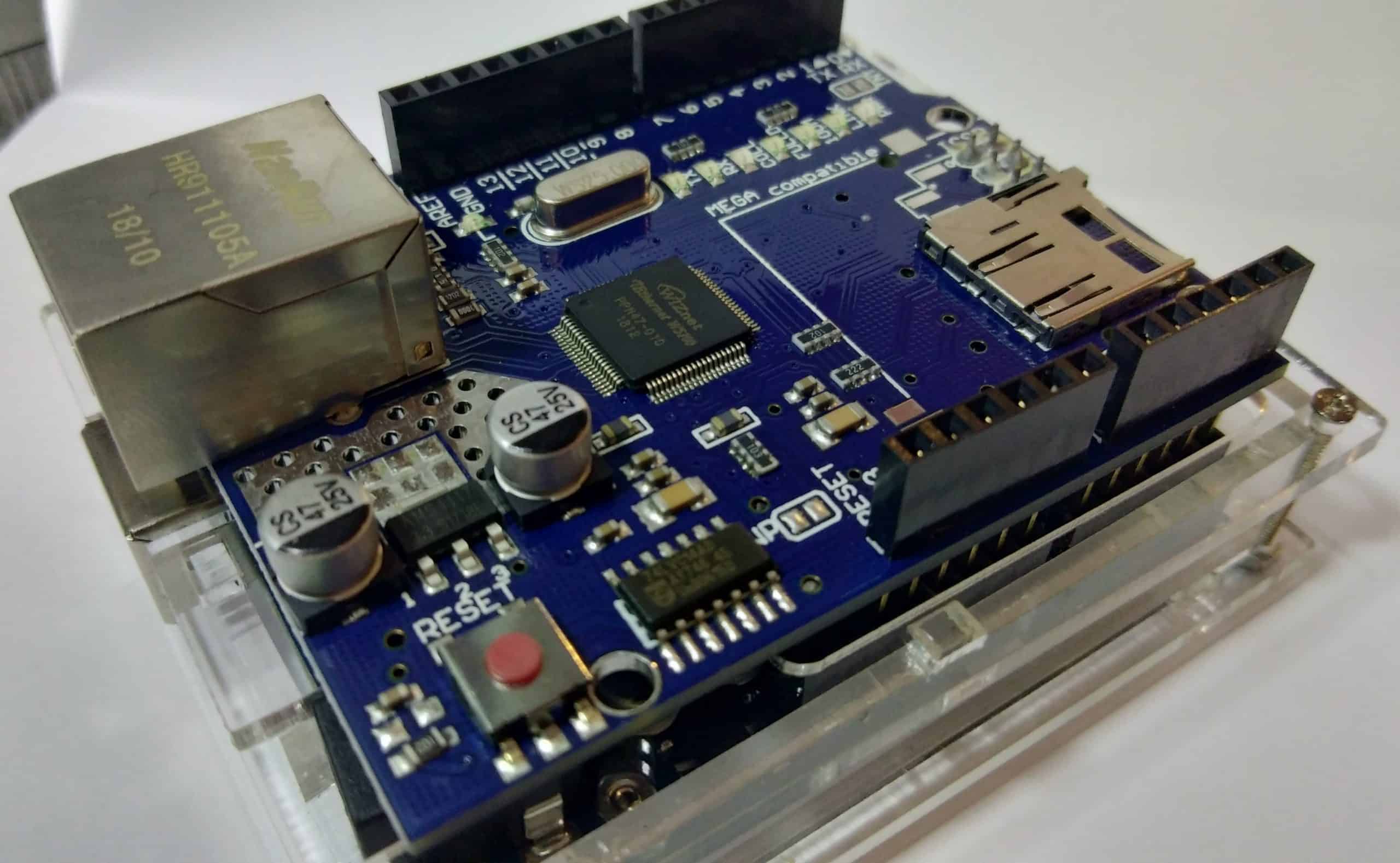
The Arduino Ethernet Shield
To reach an NTP server, first we need to find a way for the Arduino to connect to the internet.
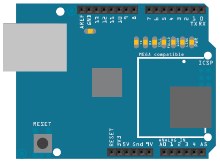
The Ethernet shield will give the Arduino board network connectivity. It has an Ethernet controller IC and can communicate to the Arduino via the SPI pins. Aside from the ethernet circuit, the board also has a microSD card module built-in. Both circuits can be accessed by pulling their respective Chip Select (CS) pin to LOW. The CS pin for the micro-SD card is pin 4.
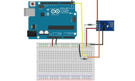
This shield can be connected to the Arduino in two ways. One way is to simply stack it on top of the Arduino. The second way is to use jumpers and connect the ICSP headers between the boards. If using wires, pin 10 is the Chip Select (CS) pin. For this tutorial, we will just stack the shield on top of the Arduino.
If you want to learn more about the Arduino, check out our Ultimate Guide to the Arduino video course. You’ll learn basic to advanced Arduino programming and circuit building techniques that will prepare you to build any project.
Arduino Sketch
For our project, we will use three libraries – the SPI library, the Time library, and the Ethernet library.
- SPI library
<SPI.h>– for communicating with the Ethernet Shield - Time Library
<TimeLib.h>– for updating and displaying the date and time - Ethernet library
<Ethernet.h>– for connecting the Arduino to the internet or a network
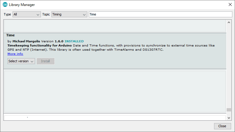
The SPI and Ethernet libraries come pre-installed with the Arduino IDE. To install the Time library, search and install the library “Time” by Michael Margolis from the IDE’s Library Manager. See Figure 2 below as a guide.
After installing the libraries into the IDE, use keyword #include to add them to our sketch.
// Using An Arduino Ethernet Shield To Get Date and Time

#include <SPI.h>         // for communication with Ethernet Shield
#include <TimeLib.h>     // for update/display of time
#include <Ethernet.h>    // for communication with NTP Server via UDP
Create Global Variables
The next step is to create global variables and objects. Some variables that are worth mentioning here are the byte mac[], the IPAddress timeSrvr(), and the byte messageBuffer[48].
The byte array mac[] contains the MAC address that will be assigned for the ethernet shield. This is a unique identifier for the shield in the network.
The IPAddress timeSrvr(address) is used to create an object with data type IPaddress. The parameter address is the IP address you want to be saved to the created IPAddress object.
For our project, we will use one of the NTP servers from https://tf.nist.gov/tf-cgi/servers.cgi. The server IP we will use is 129.6.15.28
The byte array messageBuffer[48] will contain the request and the response message to/from the NTP server.
/*
    =======================
    create global variables
    =======================
*/

// variable to hold Ethernet shield MAC address
byte mac[] = { 0xAA, 0xBB, 0xCC, 0x00, 0xFE, 0xED };

// define IPAddress object that will contain the NTP server IP address
// We will use an NTP server from https://tf.nist.gov/tf-cgi/servers.cgi
IPAddress timeSrvr(129,6,15,28);

// define Ethernet UDP object and local port 8888
EthernetUDP ethernet_UDP;
unsigned int localPort = 8888;

// variable to store previous displayed time
time_t prevDisplay = 0;

// array to hold incoming/outgoing NTP messages
// NTP time message is 48 bytes long
byte messageBuffer[48];
Initialization Inside the setup() Section
After creating global variables and objects, we will do the following.
- Initialize the Arduino serial interface with baud 9600 bps.
- Assign a MAC address to the ethernet shield.
- Get an IP address for the shield from DHCP.
- Set the function
setSyncProvider().
setSyncProvider()
The function setSyncProvider(getTimeFunction) is used by the Time Library to call the getTimeFunction at fixed intervals. In our project, the getTimeFunction is the function that request current time from the NTP server.
/*
   ============================================================
   initialize the ff. inside setup():
      1. Arduino Serial interface
      2. Ethernet shield MAC address [part of Ethernet Library]
      3. Ethernet shield IP address [part of Ethernet Library]
      4. setSyncProvider() [part of Time Library]
   ============================================================
*/

void setup()
{
  // start Arduino Serial with baud rate 9600
  Serial.begin(9600);
  delay(500);
  Serial.println("Sample Program for the Tutorial: Using An Arduino Ethernet Shield To Get Date and Time");

  // get ethernet shield IP via DHCP
  // [part of Ethernet Library]
  while (Ethernet.begin(mac) == 0) {
    Serial.println("Failed to configure Ethernet using DHCP"); // display error
    delay(1000); // retry after 1 sec
  }

  // DHCP assignment successful, display ethernet shield IP to serial
  // [part of Ethernet Library]
  Serial.print("Ethernet Shield IP (DHCP): ");
  Serial.println(Ethernet.localIP());

  // start UDP
  // [part of Ethernet Library]
  ethernet_UDP.begin(localPort);
  Serial.println("Ethernet UDP Start....");

  // pass function getTime() to Time Library to update current time
  // [part of Time Library]
  setSyncProvider(getTime);
}
After populating the setup() function, we will create code inside loop() to display the current date and time on the serial monitor.
/*
   ==================================================
   create code inside loop() to display current time
   ==================================================
*/

void loop()
{
  if (timeStatus() != timeNotSet) {   // check if the time is successfully updated
    if (now() != prevDisplay) {       // update the display only if time has changed
      prevDisplay = now();
      digitalClockDisplay();          // display the current date and time
    }
  }
}
User-Defined Functions
To make our code easy to manage, we will create functions to help us in the process of requesting, parsing, and displaying time data from the NTP server.
digitalClockDisplay() and printDigits()
The function digitalClockDisplay() and its helper function printDigits() uses the Time library functions hour(), minute(), second(), day(), month(), and year() to get parts of the time data and send it to the serial monitor for display.
/*
   ========================================================================================
   function to display the time in an easy to read format using the Time Library functions
   ========================================================================================
*/
void digitalClockDisplay() {

  Serial.print(hour());
  printDigits(minute());
  printDigits(second());
  Serial.print(" ");
  Serial.print(day());
  Serial.print(" ");
  Serial.print(month());
  Serial.print(" ");
  Serial.print(year());
  Serial.println();
}

/*
   =========================================
   helper function for digitalClockDisplay()
   =========================================
*/
void printDigits(int digits) {
  // add colon character and a leading zero if number < 10
  Serial.print(":");
  if (digits < 10)
    Serial.print('0');
  Serial.print(digits);
}
Communicating with the NTP Server
To communicate with the NTP server, we first need to send a request packet. We will initialize all 48 bytes to zero by using the function memset(). Then, we will assign values to selected indices of the array to complete a request packet. The helper function sendRequest() handles the creation of the request packet and sends it to the NTP server.
After sending the request, we wait for a response to arrive. The response can be longer than 48 bytes but we will only need the first 48 bytes. As for our code, if no response arrives after 1500 milliseconds, our function will print an error message to the serial monitor and terminate with return 0;.
Once a response packet is received, we call the function ethernet_UDP.parsePacket(). This function returns the number of bytes received and is waiting to be read. If the returned value is 48 bytes or more, we call the function ethernet_UDP.read() to save the first 48 bytes of data received to the array messageBuffer.
The response packet contains a timestamp at byte 40 to 43. This timestamp is the number of seconds elapsed since NTP epoch ( 01 January 1900 ). To get the current UTC time, we just need to subtract the seconds elapsed since the NTP epoch from the timestamp received. The Time library uses this value to calculate the hours, minutes, seconds, day, month, and year in UTC to be displayed to the serial monitor.
/*
   ===========================================
   NTP code for communicating with NTP server
   ===========================================

   =================================================
   function to request current time from NTP server
   =================================================
*/
time_t getTime()
{
  while (ethernet_UDP.parsePacket() > 0) ; // discard packets remaining to be parsed

  Serial.println("Transmit NTP Request message");

  // send packet to request time from NTP server
  sendRequest(timeSrvr);

  // wait for response
  uint32_t beginWait = millis();

  while (millis() - beginWait < 1500) {

    int size = ethernet_UDP.parsePacket();

    if (size >= 48) {
      Serial.println("Receiving NTP Response");

      // read data and save to messageBuffer
      ethernet_UDP.read(messageBuffer, 48);

      // NTP time received will be the seconds elapsed since 1 January 1900
      unsigned long secsSince1900;

      // convert to an unsigned long integer the reference timestamp found at byte 40 to 43
      secsSince1900 =  (unsigned long)messageBuffer[40] << 24;
      secsSince1900 |= (unsigned long)messageBuffer[41] << 16;
      secsSince1900 |= (unsigned long)messageBuffer[42] << 8;
      secsSince1900 |= (unsigned long)messageBuffer[43];

      // returns UTC time
      return secsSince1900 - 2208988800UL;
    }
  }

  // error if no response
  Serial.println("Error: No Response.");
  return 0;
}

/*
   helper function for getTime()
   this function sends a request packet 48 bytes long
*/
void sendRequest(IPAddress &address)
{
  // set all bytes in messageBuffer to 0
  memset(messageBuffer, 0, 48);

  // create the NTP request message

  messageBuffer[0] = 0b11100011;  // LI, Version, Mode
  messageBuffer[1] = 0;           // Stratum, or type of clock
  messageBuffer[2] = 6;           // Polling Interval
  messageBuffer[3] = 0xEC;        // Peer Clock Precision
  // array index 4 to 11 is left unchanged - 8 bytes of zero for Root Delay & Root Dispersion
  messageBuffer[12]  = 49;
  messageBuffer[13]  = 0x4E;
  messageBuffer[14]  = 49;
  messageBuffer[15]  = 52;

  // send messageBuffer to NTP server via UDP at port 123
  ethernet_UDP.beginPacket(address, 123);
  ethernet_UDP.write(messageBuffer, 48);
  ethernet_UDP.endPacket();
}
Save the sketch as Arduino-ethernet-time-tutorial.ino and upload it to your Arduino Uno.
Project Test
The Arduino Uno with Ethernet Shield is set to request the current time from the NTP server and display it to the serial monitor. So now, run our project by connecting the ethernet switch to your router via a LAN cable. Finally, connect the Arduino to the computer via USB cable and open the serial monitor.
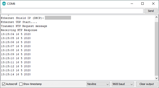
Our project will request the IP from the DHCP, request the current time from the NTP server and display it on the serial monitor. This cycle will repeat every second. Figure 4 shows the display on my serial monitor when I ran this project.
Thanks for reading, and be sure to leave a comment below if you have questions about anything or have trouble setting this up.


Nice posting,, but it’s rea.ly, really bad form to use (or recommend) the NIST servers for something like this. They are not intended for end user access (instead they serve lower stratum servers that then serve clients) and are badly overloaded as it is. Much better to enable DNS and use the pool.ntp.org service.
I’m curious how much memory was left after running that program. Enough to use the SD card? I wrote a logger applicaton using RTC and SDcard on the Adafruit logger shield and had a hell of a time getting it to fit into the Arduino.