
Using an electret microphone, the Arduino can detect sounds and perform actions based on the input it receives. For example, the sound of hands clapping, a door closing, or someone’s voice can all be used to trigger an Arduino’s output.

In this article, I’m going to show you how to set up and program a couple different types of electret microphones on the Arduino. We’ll take a look at what the output of the microphones look like, then we’ll build a circuit that responds to a loud sound by lighting up an LED.
Watch the video for this tutorial here:
What is an Electret Microphone?
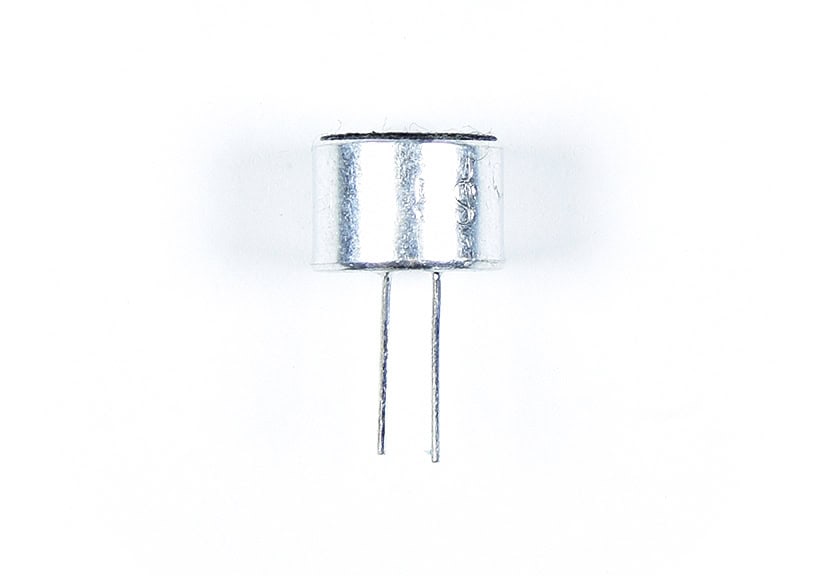
Electret microphones come packaged as a stand-alone unit like this one:
Or attached to a breakout board like this:
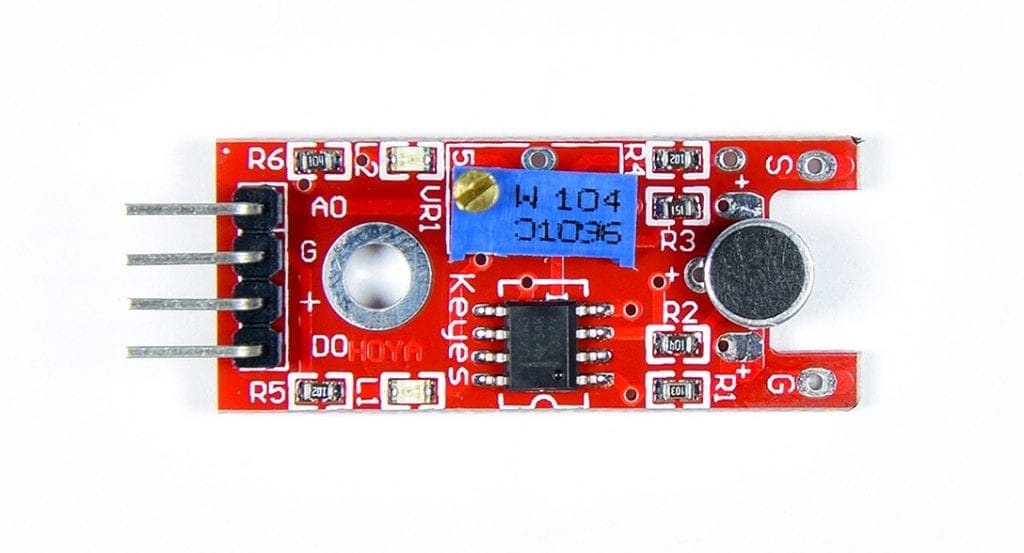
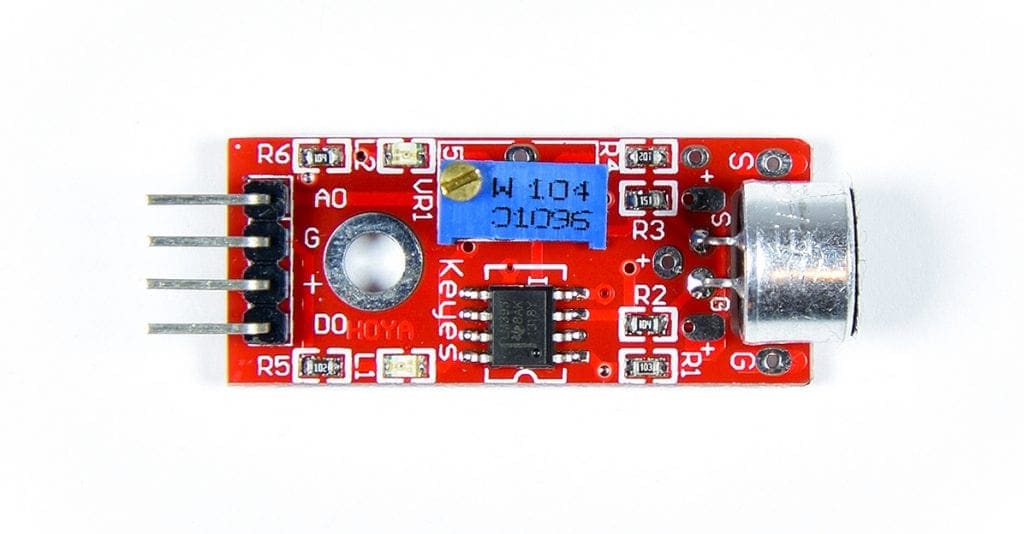
Breakout Board Microphones
The breakout board above is a Keyes KY-038 sound detector module. Breakout board microphones usually come with a pre-amplifier built in. The pre-amplifier amplifies the audio signal to a level the Arduino can work with. This board has an “analog output” and a “digital output”. The blue component in the image above is the threshold potentiometer. It sets the sensitivity of the microphone.
Stand Alone Microphones
Stand alone microphones are a little harder to set up, since they don’t have a pre amplifier. You will need to build and connect one yourself.
Electret Microphones
Electret microphones are polarized, so they have a positive pin and a ground pin:
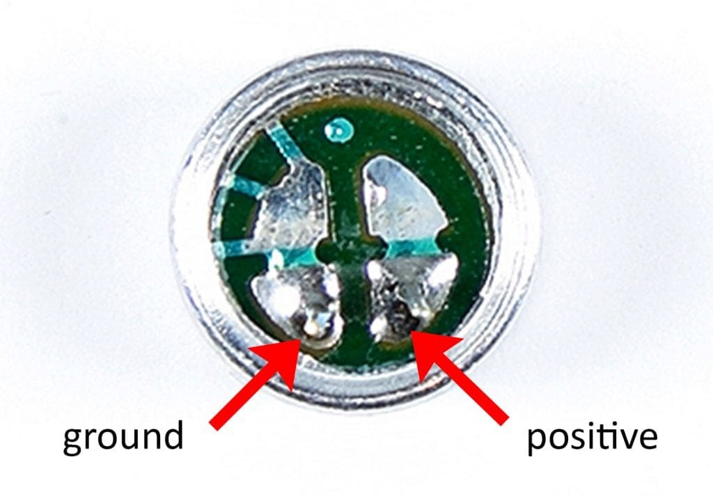
The pin that connects to the metal casing is the ground pin and the other pin is the positive pin.
How Electret Microphones Work
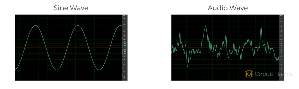
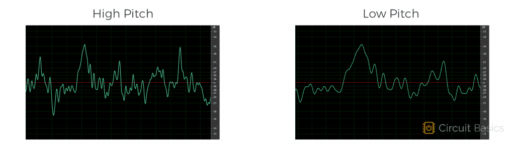
Audio signals are an alternating current, similar to the current in the electrical outlets in your home. However, while the AC current in your home is a sine wave with a static frequency and wavelength, audio waves are highly variable:
A higher frequency audio signal creates a higher pitched sound. And a lower frequency audio signal creates a lower pitched sound:
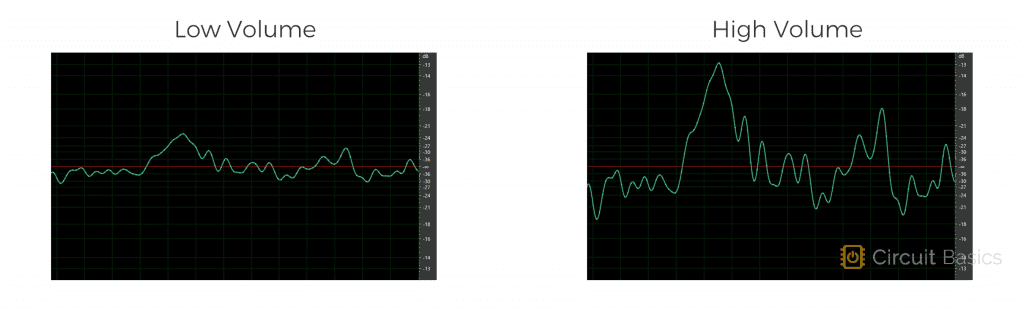
The “volume”, or “loudness” of a sound is directly related to the amplitude of the peaks. A higher amplitude audio signal creates a higher volume sound. And a lower amplitude audio signal creates a lower volume sound.
Another factor called “DC offset” determines the voltage at the waveform’s center.
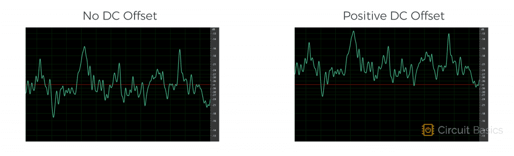
The audio signal swings up and down around the “DC offset” voltage.
How to Connect an Electret Microphone to the Arduino
Now let’s see what the raw signal from the microphone looks like. The signal output from an electret microphone is very weak, so we need to connect the microphone to a pre-amplifier to amplify the output before it’s sent to the Arduino.
What is a Pre-Amplifier?
A pre-amplifier is a circuit that increases, or amplifies a weak audio signal into a stronger one. One way to make a pre-amplifier is with one or more “operational amplifiers”, or “op-amps” for short. Op-amps are general purpose voltage amplifiers:
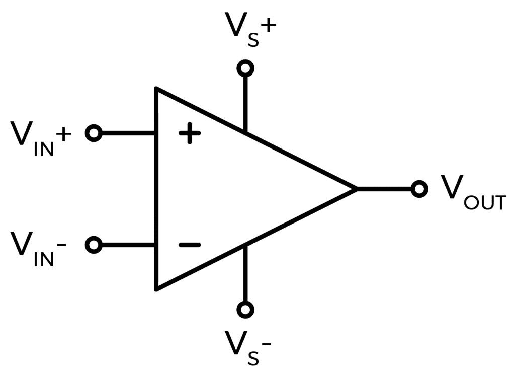
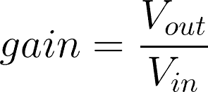
Op-amps take a low voltage input signal and output a high voltage signal. One important aspect of op-amps is the concept of “gain”. Gain is the level of amplification performed by the amplifier. It’s the ratio of the output voltage to the input voltage.
A gain of 1 would result in no amplification of the input signal, and a gain of 10 would result in a ten-fold amplification of the input signal. Gains are usually set anywhere from 1 up to about 100X. There are lots of pre-amplifier chips on the market that you can use to amplify the electret microphone’s signal. Here are some of the most common ones:
- TLC272
- LM393
- LM358
- OPA2344
- OPA2345
- LM386
In testing, I compared the popular LM386 amplifier to the LM358. The LM358 had a cleaner signal with less noise, so that’s what I’m going to use here.
How to Connect an Electret Microphone and Pre-Amp to the Arduino
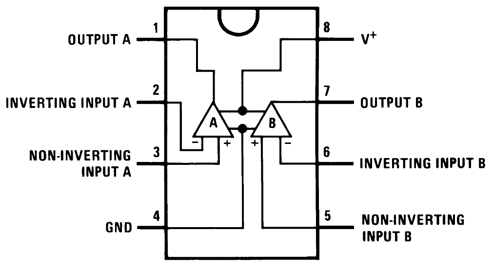
Here’s a diagram of the LM358 pins:
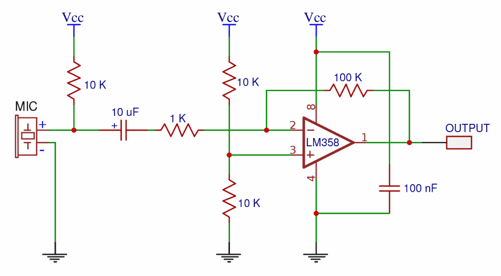
You can build the pre-amplifier circuit following this schematic:
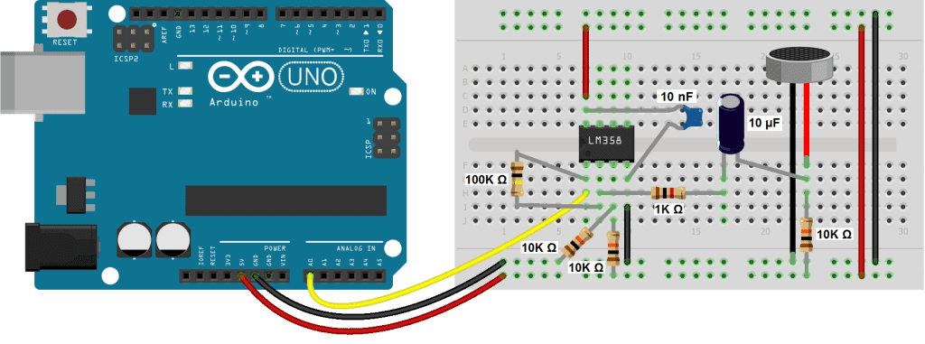
Or you can use this wiring diagram:
Here is a list of parts you will need:
- Arduino Uno
- Jumper wires
- Breadboard
- One 1K Ohm resistor
- Three 10K Ohm resistors
- One 100K Ohm resistor
- One 10 uF capacitor
- One 10 nF capacitor
- LM358 op-amp
- Electret microphone
The gain of this circuit can changed by replacing the 100K Ohm resistor with another value. When the value is 100K ohms, the gain is set at 100X, which is the highest gain the LM358 can produce. So that will make the microphone pretty sensitive. You can lower the gain by using a smaller resistor. For example, a 47K ohm resistor will set the gain at 47X. A 10K ohm resistor will set the gain at 10X.
How to Program an Electret Microphone on an Arduino
With the microphone and pre-amp connected to the Arduino, let’s take a look at the code that will detect the microphone’s output.
const int microphonePin = A0;

void setup() {
  Serial.begin(9600);
}

void loop() {
  int mn = 1024;
  int mx = 0;

  for (int i = 0; i < 10000; ++i) {

    int val = analogRead(microphonePin);

    mn = min(mn, val);
    mx = max(mx, val);
  }

  int delta = mx - mn;

  Serial.print("Min=");
  Serial.print(mn);
  Serial.print(" Max=");
  Serial.print(mx);
  Serial.print(" Delta=");
  Serial.println(delta);
}
First we declare a variable for the microphone’s input pin, and set it equal to analog pin 0. Then we initialize the serial monitor. To capture the fluctuating audio signal, we’ll take a series of analog reads from the microphone pin. Then we’ll calculate the minimum and maximum values measured in that series of analog reads.
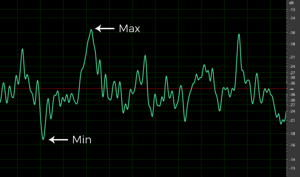
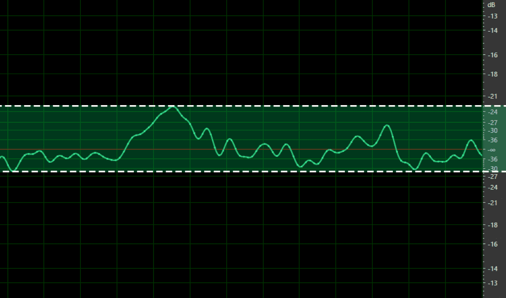
Next we’ll calculate the difference, or delta, between the minimum and maximum values. The value of the delta will give us an idea of the volume of sound detected by the microphone. A smaller delta corresponds to a smaller amplitude in the audio waveform, and thus a quieter sound:
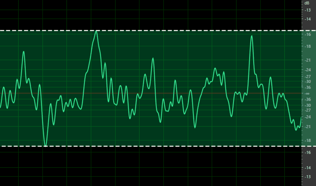
A larger delta corresponds to a larger amplitude waveform, and a louder sound:
Explanation of the Code
In the loop section, we start by declaring a variable called mn, which will store the minimum value of the analog reads. It’s initially set equal to 1024. Then we declare a variable called mx, which will store the maximum analog read values. It’s initially set equal to zero.
Next we have a for statement. The condition of the for statement creates a loop that runs 10,000 times before exiting. Each time the loop iterates, an analog read is taken from the microphone pin, and stored in the local variable, val.
After each analog read, we calculate the minimum and maximum values measured within those 10,000 analog reads.
The min() Function
The min() function takes two parameters, and returns the one with the smallest value. In this case the parameters are variables, mn and val. For example, if mn = 1, and val = 5, the min() function will return 1, since it’s smaller than 5.
The max() Function
The max() function works the same way as the min() function, but returns the larger of the two parameters. So if mx is larger than val, it will return mx. If val is larger than mx, it will return val.
So how does the for loop return the min and max analog read values over a series of 10,000 reads? The first time through the loop, mn is set equal to 1024, and mx is set equal to zero. In the first iteration through the for loop, we take an analog read of the microphone pin, and store the reading in val. Let’s say it’s 620. The min() function compares 1024 to 620 and returns the smaller value, so 620 is now stored in the mn variable. Then the max() function compares 0 to 620, and returns the higher value. So 620 is now stored in the mx variable.
Now the for loop iterates a second time. Another analog read is taken from the microphone pin and stored in the val variable. Let’s say now it’s 340. The min() function now compares 620 to 340 and returns the smaller value. So this time 340 is stored in the mn variable. When the max() function is executed, it compares 620 to 340 and returns the higher value. This time 620 is still higher than 340, so the value stored in mx is still 620. This process repeats until the 10,000th iteration, at which point it exits the loop with the highest and lowest analog read values stored in mx and mn.
To get the delta, or difference between the highest and lowest reading, we simply subtract mx from mn. After that, we can print mn, mx, and delta to the serial monitor.
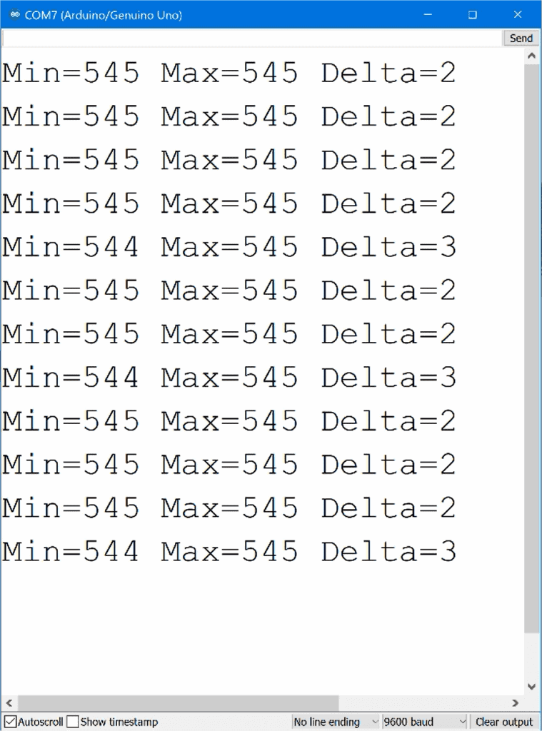
After you build the circuit and upload the code, open the serial monitor and you will see Min, Max, and Delta values being printed out:
How to Setup Microphone Breakout Boards on the Arduino
Now let’s look at how to set up the breakout board style of microphone. These are quite a bit easier to set up since they have a pre-amplifier built in. We’ll be using the Keyes KY-038 microphone module:
The Keyes KY-038 uses an LM393 op-amp. The module has four pins. The A0 pin carries the amplified analog audio output. G is for ground, the “+” sign is Vcc, and the D0 pin is the digital output.
The digital output is LOW when the audio signal is lower than a certain threshold value, and HIGH when the audio signal is greater than a certain threshold value.
The threshold value can be changed by adjusting the screw on top of the blue potentiometer. Turning the screw clockwise decreases the threshold and makes the microphone more sensitive. Turning it counter-clockwise increases the threshold and makes the microphone less sensitive.
How to Use the Microphone Module’s Digital Output to Trigger an Event
To demonstrate how to use the microphone’s digital output, let’s build an example project that reads the digital signal from the microphone and turns on an LED when the sound level increases above a certain threshold value.
Here are the parts you will need:
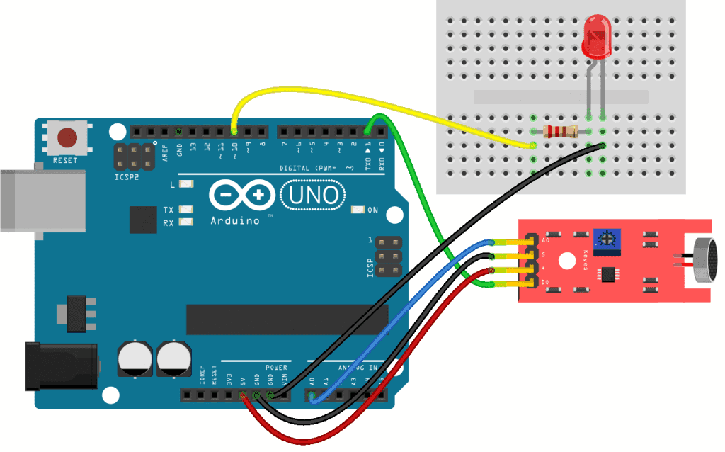
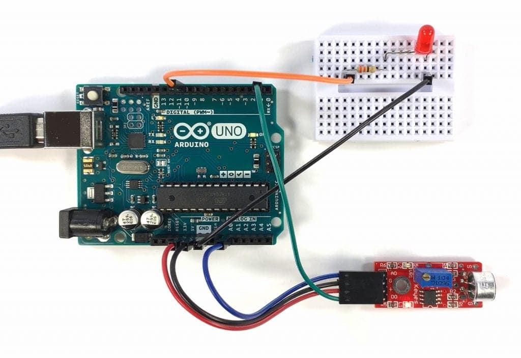
Follow this diagram to connect the microphone module and LED to the Arduino:
In the sketch below, we’re going to take a digital read from the microphone’s digital pin. If the reading is HIGH, we’ll digital write a HIGH value to the LED.
int ledPin = 10;
int microphonePin = 1;
int state = 0;

void setup() {
  pinMode(ledPin, OUTPUT);
  pinMode(microphonePin, INPUT);
}

void loop() {
  state = digitalRead(microphonePin);

  if (state == HIGH) {
    digitalWrite(ledPin, HIGH);
    delay(1000);
  }

  else {
    digitalWrite(ledPin, LOW);
  }
}
Explanation of the Code
At the top of the sketch, we declare variables for the microphonePin and ledPin. We also declare another variable called state, to store the HIGH and LOW values read from the microphone’s digital pin.
In the setup() section, we initialize the ledPin as an OUTPUT, and the microphonePin as an INPUT. In the loop() section, we first take a digital read from the microphonePin and store that reading in the state variable. Then we have an if else statement that says “if the microphone pin state is HIGH, then digital write the ledPin HIGH, and delay for one second”. Otherwise, digital write the ledPin LOW.
Once the microphone module and LED are connected to your Arduino, upload the code. When you make a loud sound, the LED should light up:
Ok, now let’s look at how to trigger an LED with the microphone’s analog signal.
How to Use the Microphone Module’s Analog Output to Trigger an Event
For this example, connect the microphone module and LED the same way you did in the last example. In the sketch below, the Arduino will calculate the min, max, and delta values from a series of analog reads from the microphone. We’ll use the delta value to trigger a digital write to the LED pin:
const int microphonePin = A0;
int ledPin = 10;

void setup() {
  Serial.begin(9600);
  pinMode(ledPin, OUTPUT);
}

void loop() {
  int mn = 1024;
  int mx = 0;

  for (int i = 0; i < 100; ++i) {
    int val = analogRead(microphonePin);
    mn = min(mn, val);
    mx = max(mx, val);
  }

  int delta = mx - mn;

  Serial.println(delta);

  if (delta > 200) {
    digitalWrite(ledPin, HIGH);
    delay(1000);
  }

  else {
    digitalWrite(ledPin, LOW);
  }
}
Explanation of the Code
First we declare the microphonePin and ledPin variables. When adjusting the sensitivity, it helps to print the delta values to the serial monitor, so we’ll initialize that as well.
In the setup() section, we initialize the serial monitor and set the ledPin as an OUTPUT.
In the loop() section, we declare variables for mn and mx. Then we have a for loop that takes a bunch of reads, and calculates the min and max analog read values from the microphonePin. In the pre-amplifier sketch we saw earlier, we performed 10,000 iterations of the for loop. But 10,000 iterations creates a delay in how the LED responds. So you can decrease this to 100, which still works fine:
for (int i = 0; i < 100; ++i) {
Next we calculate the delta, just like before. Then we print delta to the serial monitor.
After that, we use an if statement to set the threshold to control when the LED lights up. For example, if delta is greater than 200, then we digital write the ledPin HIGH, and delay for one second. Otherwise, we digital write the ledPin LOW with an else statement. The number 200 sets the threshold that triggers the LED:
if (delta > 200) {
A lower threshold will make the LED turn on at a lower sound level. And a higher threshold will make the LED turn on at a higher sound level. Play around with different threshold values to get the microphone to respond to different types of sounds, and remember that the LED can be substituted with any other device that can be activated with a high or low signal!
Feel free to leave a comment below if you have a question about anything…

Very good two tutorials in one extending the use and learning of Arduino many thanks
Excellent tutorial for exposing power of Arduino Uno. Code has some good examples of how to expand capabilities of the Uno. I’m trying to think of how I might use this at Halloween.
Very good site, on which you can learn a lot about Arduinos and also implement them!
Many Thanks from Germany
You have really made the Arduino lessons very simple, practical and easy to read and understand, such that even persons with no or little coding or programming skills as well as electronics skills or technical experience can follow through and perform all the experiments.
Is there any way to record voice to output to speakers?
สำรวจ โอกาส การลงทุน ที่น่าตื่นเต้น
กับ Maxbet แพลตฟอร์ม ยอดนิยม ซึ่งเป็นที่
นำเสนอ การแข่งขัน การทายผล นานาชนิด ชนิด ตั้งแต่การ
การเล่นกีฬา เป็นที่ชื่นชอบ เช่น บอล บาสฯ เทนนิสฯ รวมถึง คาสิโน ทางอินเทอร์เน็ต ที่ซึ่ง
ส่งมอบ ความสุข อย่างไม่มีที่สิ้นสุด Maxbet ยังคง เสนอ โบนัส เป็นพิเศษ แก่ ผู้สมัครใหม่ ตลอดจน นักพนัน ประจำ ด้วยเช่นกัน