
Before we dive into our main topic, let us first discuss what are shift registers used for. Shift registers have many uses – converting data from series to parallel format (in communication systems, for example), and the reverse of this, up/down counters, ring counters, sequence generators, time delays, and data storage, just to name a few. They are everywhere and very old. It was in 1944 in Bletchly Park in the UK when Tommy Flowers of the GPO built the world’s first shift register using valves (tubes). You can read more about that here.

If you have a project which consumes a lot of pins on an Arduino Uno – perhaps you’re already using pins for an LCD display, and you need more to add an array of 8 LEDs, but there are not enough pins left – what you need is a shift register.
In other words, shift registers are sequential logic circuits, capable of storage and transfer of data.
SIPO and PISO Shift Registers
Shift registers come in two main types, a SIPO (Serial-In-Parallel-Out) or PISO (Parallel-In-Serial-Out). The standard SIPO chip is a 74HC595 shift register, and the PISO chip is a 74HC165 shift register. A SIPO is useful for driving a large number of outputs, like LEDs, or 7 segment displays, and a PISO is useful for gathering a large number of inputs, like buttons.
Using SIPO and PISO
An understanding of some bitwise Arduino manipulation is helpful to using SIPO and PISO. To illustrate this better, we will build some example projects. For sketch 1, we will use the PISO 74HC165 connected to 4 input DIP switches. This will read the parallel value on the switches out to the serial port.
For sketch 2, we will use the SIPO 74HC595 to control 8 LEDs on the output and make a simple running light display. And finally, for sketch 3, we will use again the SIPO 74HC595 to write some patterns to the LEDs, but this time, using a pattern array.
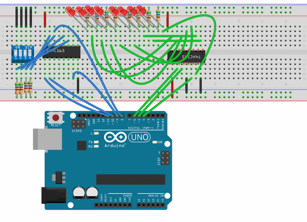
Wiring Up the Shift Registers to the Arduino
Here are the parts you will need:
- Arduino Uno
- Jumper wires
- Breadboard
- One 74HC595 SIPO shift register
- One 74HC165 PISO shift register
- Eight 220 Ohm current limiting resistors
- Four 5.6K Ohm pull up resistors
- One 4-position DIP switch
The 74HC165 is the chip on the left, and the 74HC595 is the switch on the right:
To learn more about the Arduino, check out our Ultimate Guide to the Arduino video course. We teach Arduino programming and circuit building techniques that will prepare you to build any project.
Notes on the Sketches
There are no libraries to install. All we need are the three sketches below.
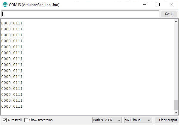
Sketch 1 is a PISO. It loads the value of the nibble (a nibble is half a byte), where the switches are set at, into the register, and clocks them out serially. The serial output is to the Arduino serial window, but this might not be apparent. The Arduino will not print leading zeros on a binary number, so I have included a function printBin() that will do this. The function also formats the print with the right space between nibbles. Because of the way I wired mine, the data I wanted comes out in the MSN (Most Significant Nibble), so I use >>4 to get it into the LSN. All the clocking and shifting is done by pulsing the clockIn and dataIn pins and then using the shiftIn() function.
Sketch 2 is a SIPO. We write a serial data stream in by using the initial state of i=0 and then clock that through the register and using bitset() to turn the bits on. The function shiftLED() does the hard work of latching and clocking the log for us.
Sketch 3 is a different approach. Here, a bit pattern is stored in an array, and this is passed on to shiftLED bit by bit to create a pattern. I have given you two patterns but comment them out one at a time.
Arduino Code for Sketch 1 (PISO)
//reads dip sws and displays on serial monitor
// Define Connections to 74HC165
int load = 11; // PL pin 1
int clockEnablePin = 8; // CE pin 15
int dataIn = 9;// Q7 pin 7
int clockIn = 10; // CP pin 2
/////////////////////////////////////
void setup()
{
  Serial.begin(9600);
  // Setup 74HC165 connections
  pinMode(load, OUTPUT);
  pinMode(clockEnablePin, OUTPUT);
  pinMode(clockIn, OUTPUT);
  pinMode(dataIn, INPUT);
}
 /////////////////////////////////////
void loop()
{
  // Write pulse to load pin
  digitalWrite(load, LOW);
  delayMicroseconds(5);
  digitalWrite(load, HIGH);
  delayMicroseconds(5);

  // Get data from 74HC165
  digitalWrite(clockIn, HIGH);
  digitalWrite(clockEnablePin, LOW);
  byte incoming = shiftIn(dataIn, clockIn, LSBFIRST);
  digitalWrite(clockEnablePin, HIGH);

  // Print to serial monitor
 // incoming = incoming & 0B11110000; //mask off and get rid of lsb
 //not required as 0's get shifted in
  incoming = incoming >> 4; //move msb to lsb
  printBin(incoming);
  //note you can invert the  logic with ~incoming
  delay(200);
}
///////////////////////////////////////////
void printBin(byte inByte)
//if you try print 00011101 you will get 1101 as the leading zeros don't print
//this prints a bin number with all the leading zeros and a space between nibbles
{
  for (int b = 7; b >= 4; b--)
      Serial.print(bitRead(inByte, b));
      Serial.print(" ");
  for (int b = 3; b >= 0; b--)
      Serial.print(bitRead(inByte, b));  //now prints:  0001 1101
  Serial.println(); //needs a CR at end
}
////////////////////////////////////////////
Arduino Code for Sketch 2 (SIPO)
int latchPin = 5;
int clkPin = 6;
int dataPin = 4;
byte LED = 0;
byte i=0;
//////////////////////////////////////////////////////
void setup()
{
  Serial.begin(9600);
  pinMode(latchPin, OUTPUT);
  pinMode(dataPin, OUTPUT);
  pinMode(clkPin, OUTPUT);
}
//////////////////////////////////////////////////////
void loop()
{
  //single LED running light
  LED = 0; //lsbit
  if(i==8)
      i=0;
  bitSet(LED, i);
  Serial.println(i);
  shiftLED(LED);
   i++;
  delay(300);
}
//////////////////////////////////////////////////
void shiftLED(byte thisLED)
{
   digitalWrite(latchPin, LOW);
   shiftOut(dataPin, clkPin, MSBFIRST, thisLED);
   digitalWrite(latchPin, HIGH);
}
//////////////////////////////////////////////
Arduino Code for Sketch 3 (SIPO With Pattern Array)
// Define Connections to 74HC595
const int latchPin = 5;// ST_CP pin 12
const int clockPin = 6; // SH_CP pin 11
const int dataPin = 4; // DS pin 14
int pattern[8];
///////////////////////////////////////////////
void setup()
{
  pinMode(latchPin,OUTPUT);
  pinMode(clockPin,OUTPUT);
  pinMode(dataPin,OUTPUT);

  //pattern arrays
  pattern[0] = B10101010;
  pattern[1] = B01010101;
  pattern[2] = B10101010;
  pattern[3] = B01010101;
  pattern[4] = B10101010;
  pattern[5] = B01010101;
  pattern[6] = B10101010;
  pattern[7] = B01010101;

//  pattern[0] = B00000001;
//  pattern[1] = B00000010;
//  pattern[2] = B00000100;
//  pattern[3] = B00001000;
//  pattern[4] = B00010000;
//  pattern[6] = B01000000;
//  pattern[7] = B10000000;

}
////////////////////////////////////////////////
void loop()
{
 for(int num = 0; num < 8; num++)
  {
    shiftLED(pattern[num]);
    delay(200);
  }
}
//////////////////////////////////////////////
void shiftLED(byte thisLED)
{
   digitalWrite(latchPin, LOW);
   shiftOut(dataPin, clockPin, MSBFIRST, thisLED);
   digitalWrite(latchPin, HIGH);
}
//////////////////////////////////////////////
Output and Results
Hope this article has given you a better idea about what a shift register is and how to use them on the Arduino. Be sure to leave a comment below if you have questions about anything!

You should be able to use the SPI library to read and write these chips more easily.
I agree with Brian. I consider myself reasonably competent but what’s LSN?
Also frustrated by articles which are not checked for grammar.
Less Significant Nibble
This is the right blog for anyone who would like to find out about this topic. You understand so much its almost hard to argue with you (not that I actually will need to…HaHa). You definitely put a brand new spin on a subject which has been discussed for ages. Great stuff, just wonderful!