Some Arduino projects are designed to operate off the grid. Operating an Arduino remotely requires powering it with batteries or solar power. In these cases, power consumption becomes a critical factor, and your circuits should be optimized to reduce power consumption as much as possible.

In this article, we will discuss methods to reduce power consumption in an Arduino project. To demonstrate these methods, we will build a low power Arduino project that detects temperature and humidity with a DHT22 sensor and stores the sensor readings in an EEPROM memory chip.
Power Saving Hardware Modifications
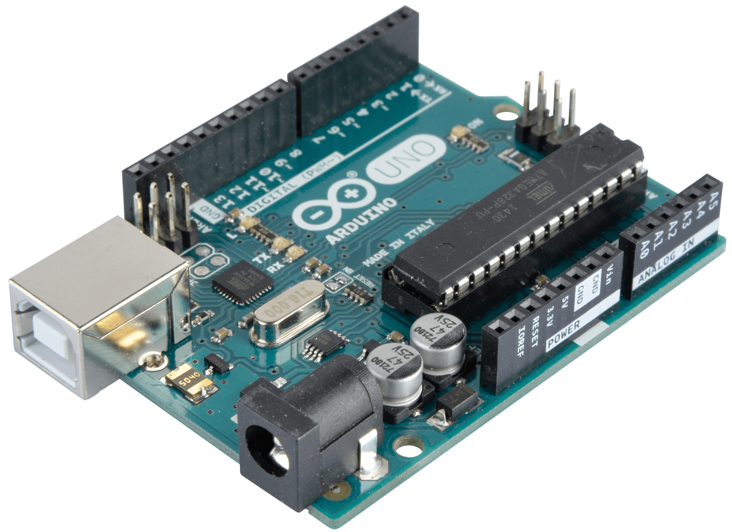
The Arduino UNO is a fantastic platform that allows users to create and test countless devices. However, the design did not concern itself with power consumption. So if you’re running your project from a 12V power supply, it will draw over 50ma of current. By lowering the voltage to a 9V battery, you can reduce the current draw to about 33ma. At that rate, you’ll be changing batteries often, something not very convenient in remote locations.
There are modifications you can make to the hardware to help reduce the current draw. For instance, given that an LED can draw as much as 2ma, you might consider removing them altogether.
Also, powering the attached devices through an I/O port allows you to turn off the device when it’s not in use. In the example project, we are going to connect the sensor the GPIO pins and only turn them on when we need to take a reading. This lowers power consumption and increases the life of the sensor.
However, some devices cannot be powered down when idle. For example, if you are using an SD card reader, it won’t allow you to turn it off then back on using a GPIO pin. Additionally, some devices like a real time clock module need to remain powered on, and you must be aware of the current limitation of an I/O port (approximately 40 ma).
The Arduino UNO uses a linear voltage regulator that is effective but not very efficient. Since the on-board power regulator is inefficient, it becomes easier to bypass. A linear regulator takes any additional voltage and dissipates it as heat. So by running your Arduino with a 9-V battery, the regulator basically turns the extra 4V into heat. This wastes about 44% of the power. The wasted power is even greater if you use a 12V supply.
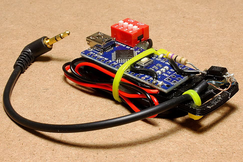
The device shown below is a 4.5-24V DC to 5V DC step-down buck converter, which is considerably more efficient than the linear regulator used on the UNO. This module takes a voltage from 4.5 volts to 24 volts and reduces it to 5 volts. The circuit should work with any step-down buck converter that has a 5V or 3.3V output. It has an additional advantage because you can disable the power output by simply grounding the enable pin (yellow wire).
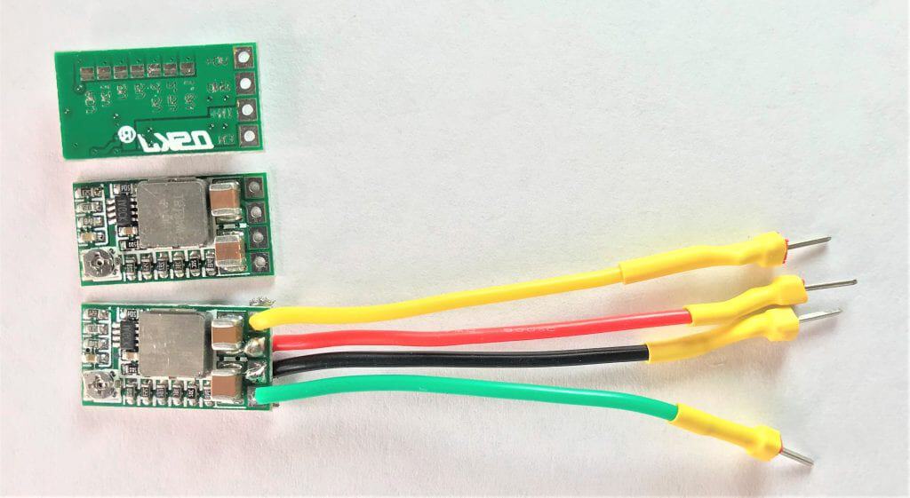
In the diagram, the black wire is common ground, and the red is the input voltage. The green wire is the voltage output.
Bypassing the onboard voltage regulator on the Arduino with a buck converter drops the current from 52ma to about 23ma:
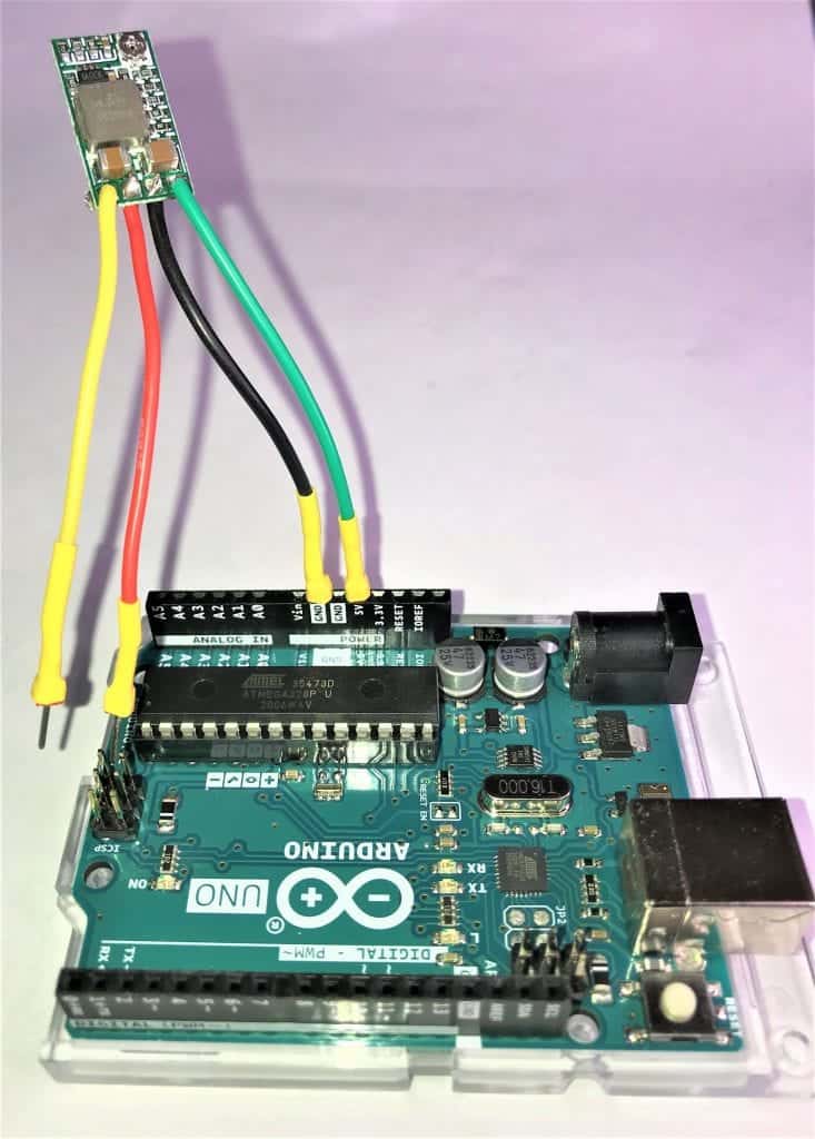
Note that the output goes to the 5V plug from the buck converter. If you decide to run the Arduino on 3.3V, use a 5V connection also. When you bypass the power plug, you are also bypassing the reverse polarity diode, so be certain you properly orient the wires.
Power Saving Software Modifications
The Arduino’s ATMEGA328 microprocessor has several power saving features built-in. We can use the LowPower Arduino library to take advantage of these features by disabling certain processes and even shutting down the processor as needed to save a considerable amount of power.
Here are the results of adding the LowPower Arduino Library to the Blink program. The results below are from identical Arduino UNOs running at 12V using the onboard regulator, and 12V on a buck converter:
| Current draw without LowPower library | Current draw with LowPower library |
| 12V using onboard voltage regulator = 50 ma | 12V using onboard voltage regulator = 45 ma |
| 5V buck converter = 27 ma | 5V buck converter = 25 ma |
| 3.3V buck converter = 10 ma | 3.3V buck converter = 8 ma |
How to Use the LowPower Library
To demonstrate the power-saving capabilities, the Blink program was modified, replacing the two delay() functions with the LowPower library functions. Below shows the function, LowPower.powerDown(SLEEP_2S, ADC_OFF, BOD_OFF);. By replacing the delay() function, it accomplished quite a bit.
#include <LowPower.h>
void setup() {
   pinMode(LED_BUILTIN, OUTPUT);
}
void loop() {
  digitalWrite(LED_BUILTIN, HIGH);
  LowPower.powerDown(SLEEP_2S, ADC_OFF, BOD_OFF);
  digitalWrite(LED_BUILTIN, LOW);
  LowPower.powerDown(SLEEP_2S, ADC_OFF, BOD_OFF);
}
The first argument, SLEEP_2S, puts the processor to sleep for two seconds. To free up the processor, the PWM signal is created on an external clock, which is disabled, turning off the ADC function saving additional power. The Brown Out Timer (BOT), used to ensure the proper voltage is provided, is also temporarily disabled.
Sleep duration can be set to 15 ms, 30 ms, 60 ms, 120 ms, 250 ms, 500 ms, 1 Second, 2 seconds, 4 seconds, or 8 seconds. There are methods of increasing the sleep duration well beyond 8 seconds, as shown later in this article.
There are numerous other methods available to control power consumption by the ATmega328P. For simplicity, we will use the LowPower.powerDown() method.
Low Power Temperature and Humidity Tracking Arduino
In this project, we will use a DHT22 sensor to read the humidity and temperature, then store the measurements on an EEPROM chip. We will also use a real time clock to attach a time and date stamp to each sensor reading.
These are the components you will need to build this project:
- Arduino Uno, Nano, or Mini
- DHT11 or DHT22 temperature and humidity sensor
- AT24C256 EEPROM
- Real-time clock module DS3231
- 5V step-down buck converter
- 10K resistor
- Breadboard
- Jumper wires
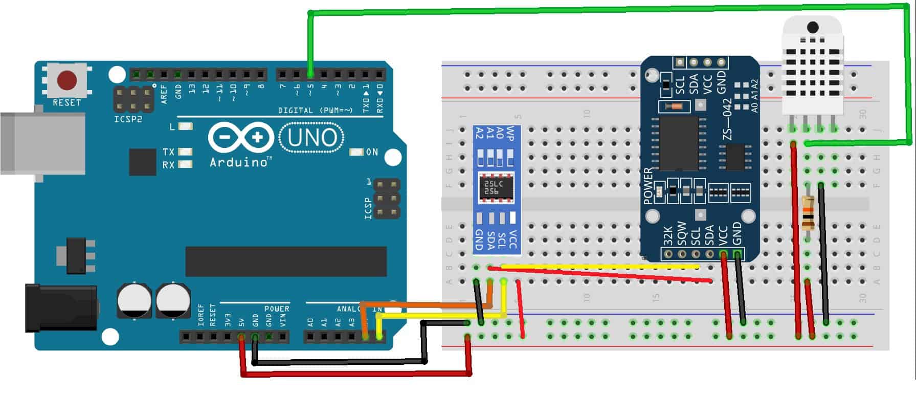
The AT24C256 comes pre-programmed from the factory with a hexadecimal address of 0x50. Once you have all of the parts, connect everything together following this wiring diagram:

To learn more about the Arduino, check out our Ultimate Guide to the Arduino video course. We teach Arduino programming and circuit building techniques that will prepare you to build any project.
How the Project Works
As mentioned, we will use an Electrically Erasable Programmable Read-Only Memory (EEPROM) to store the DHT22 sensor data. Alternatively, we could use an SD card reader. However, an SD card reader requires nearly 30ma and would use more power than the entire project. The EEPROM is the best fit for storing data in remote locations. They are small, reliable, and consume less than 3ma when writing to it. The data stored on it is non-volatile, meaning that it can be retrieved after power has been removed from the chip.
We need three separate Arduino programs. The first program is used to write the sensor data to the EEPROM. The second program is used to read the sensor data from the EEPROM. The third program is used to delete the sensor data from the EEPROM.
Code to Write the Sensor Data
// Code For storing DHT Temp and Humidity to EEPROM
#include <DHT.h>
#include <LowPower.h>
#include <Wire.h>
#include <EEPROM.h>
#include <RTClib.h>
RTC_DS1307 rtc;
#define Led 13
#define DHTPIN 5
//#define DHTTYPE DHT11
#define DHTTYPE DHT22
DHT dht(DHTPIN, DHTTYPE);
int address = 0;
void setup() {
  Serial.begin(9600);
  if (! rtc.begin()) {
    Serial.println("Couldn't find RTC");
    while (1);
  }
  //uncomment the next line to set date,then comment it out and recompile program
  //rtc.adjust(DateTime(F(__DATE__), F(__TIME__)));

  if (!rtc.isrunning()) {
    Serial.println("RTC Not running!");
  }
  dht.begin();
  Wire.begin();
} // End setup()

void loop() {
  delay(500);
  DateTime now = rtc.now();
  float h = dht.readHumidity();
  delay(500);
  float t = dht.readTemperature();
  delay(500);
  float f = dht.readTemperature(true);
  delay(500);
  EEPROM.update(address, (now.month()));
  address++;
  delay(500);
  EEPROM.update(address,(now.day()));
  address++;
  delay(500);
  EEPROM.update(address,(now.hour()));
  address++;
  delay(500);
  EEPROM.update(address,(now.minute()));
  address++;
  delay(500);
  EEPROM.update(address,h);
  address++;
  delay(500);
  EEPROM.update(address,f);
  address++;
  delay(500);
//Included to allow you to view your output
  Serial.print("Humidity:" );
  Serial.println(h);
  Serial.print("Temperature:");
  Serial.println(f);
  Serial.print("Time ");
  Serial.print(now.hour());
  Serial.print(":");
  Serial.println(now.minute());
  delay(1000);
  // Timer delays about 15 minutes between readings
  for (int i = 0; i < 100; i++) {
    LowPower.powerDown(SLEEP_8S, ADC_OFF, BOD_OFF);
  }
}
Explanation of the Code
The #include statements load the required DHT sensor libraries, LowPower library, Wire.h for the I2C bus, the EEPROM module, and the real time clock library. The DHTPIN is connected to pin 5; you need to uncomment the line that defines which device you’re using, DHT 22, in this example.
In the setup() function, the serial port is enabled, and the real time clock functionality is confirmed. Take note of the line //rtc.adjust(DateTime(F(DATE), F(TIME)));, as this is used to set the RTC against the clock your computer is using. It must be un-commented once then uploaded to set the clock. Once you have reset the clock, insert the comment again and recompile the code. The final two lines in setup enable the DHT sensor and turn on the I2C Bus.
In the loop() function after the delay(), the first instruction is to get the time from the RTC with a call to rtc.how(). The next two reads are from the DHT library using the dht.readHumidity(), dht.readTemperature() functions, that store the output in variables “h” and “t” respectively. The delays that come after the read functions are added because they have a slight delay when they read. The function dht.readTemperature(true) saves the temperature in Fahrenheit and stores it in “f”. If you prefer to use Celsius, change the variable to “t”, to replace the “f” EEPROM.update(address,f);.
The variable address declared initially as an int “0” is used to address the first storage location in the EEPROM address 0. The syntax for writing to the EEPROM is EEPROM.update(address,(value). Using EEPROM.update will first verify and write only if the data is different from what may have already been written at that address earlier. This prevents writing the same data to the location; if the data hasn’t changed, don’t rewrite it. Since you only have a finite number of times you can write to a location, this helps the device’s longevity. Memory cells can be written to approximately 100,000 times.
After writing to the first address “0”, the address is incremented, and the next cell can be written to “1”. Notice that we are writing exactly 6 chunks of data for each sampling.
The LowPower function has a maximum limit of eight seconds. We set up a for loop to loop 100 times through the LowPower stage giving us a delay of a little over 13 minutes. The times can be increased or decreased to account for whatever sampling time you want to use.
Code to Read the Sensor Data
#include <EEPROM.h>
int i = 0;
int address = 0;
byte value;
void setup() {
Serial.begin(9600);
while (!Serial) {
}
}
void loop() {
value = EEPROM.read(address);
while (value > 1) {
for (i = 0; i < 6; i++) {
Serial.print("Date-");
Serial.print(value);
Serial.print("/");
address++;
value = EEPROM.read(address);
delay(50);
Serial.println(value);
address++;
value = EEPROM.read(address);
delay(50);
Serial.print("Hours:");
Serial.print(value);
address++;
value = EEPROM.read(address);
delay(50);
Serial.print(" Minutes:");
Serial.println(value);
address++;
value = EEPROM.read(address);
delay(50);
Serial.print("Humidity:");
Serial.print(value);
Serial.println("%");
address++;
value = EEPROM.read(address);
delay(50);
Serial.print("Temperature:");
Serial.print(value);
Serial.println(" Degrees Fahrenheit");
address++;
Serial.println("\n");
break;
}
break;
}
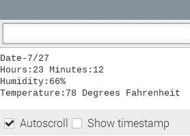
}Explanation of the Code
After breaking down the first program, this one is pretty basic. The function used to enter data was EEPROM.update(). Now, we will use the function EEPROM.read(). In the void loop(), we set up a while loop based on the contents at address 0 of the EEPROM. The first piece of data entered is the month, which should be anything from 1-12. Be sure that your RTC is running; if it isn’t, the while loop would never start. The while loop will run until it reaches the last cell written to.
The for loop was configured to read six records. That’s how many entries are made each time the data capturing program runs. If you wanted to increase the amount of data captured, you would first modify the data capturing program by adding anything else you want to be recorded. Then increase the number on the if statement to account for the extra.
Code to Erase the Sensor Data
#include <EEPROM.h>

void setup() {
  // initialize the LED pin as an output.
  pinMode(13, OUTPUT);

  for (int i = 0 ; i < EEPROM.length() ; i++) {
    EEPROM.write(i, 0);
  }

  // turn the LED on when we're done
  digitalWrite(13, HIGH);
}

void loop() {

}
Explanation of the Code
This program erases all of the data stored on the EEPROM. With reference to the LED digitalWrite(13, HIGH);, the LED is turned on to indicate that the EEPROM has been completely erased. Run this program before starting any new sampling.
Thanks for reading and be sure to leave a comment below if you have questions about anything!