
Connecting an LCD to your Raspberry Pi will spice up almost any project, but what if your pins are tied up with connections to other modules? No problem, just connect your LCD with I2C, it only uses two pins (well, four if you count the ground and power).

In this tutorial, I’ll show you everything you need to set up an LCD using I2C, but if you want to learn more about I2C and the details of how it works, check out our article Basics of the I2C Communication Protocol.
There are a couple ways to use I2C to connect an LCD to the Raspberry Pi. The simplest is to get an LCD with an I2C backpack. But the hardcore DIY way is to use a standard HD44780 LCD and connect it to the Pi via a chip called the PCF8574.
The PCF8574 converts the I2C signal sent from the Pi into a parallel signal that can be used by the LCD. Most I2C LCDs use the PCF8574 anyway. I’ll explain how to connect it both ways in a minute.
I’ll also show you how to program the LCD using Python, and provide examples for how to print and position the text, clear the screen, scroll text, print data from a sensor, print the date and time, and print the IP address of your Pi.
If you don’t have an I2C enabled LCD or a PCF8574, these tutorials will show you how to connect an LCD with the GPIO pins:
- How to Setup an LCD on the Raspberry Pi and Program it With C
- How to Setup an LCD on the Raspberry Pi and Program it With Python
Here’s the video version of this tutorial, where I go through the setup and show all of the programming examples below:
Connect the LCD
I2C (inter-integrated circuit) is also known as the two-wire interface since it only uses two wires to send and receive data. Actually it takes four if you count the Vcc and ground wires, but the power could always come from another source.
Connecting an I2C Enabled LCD
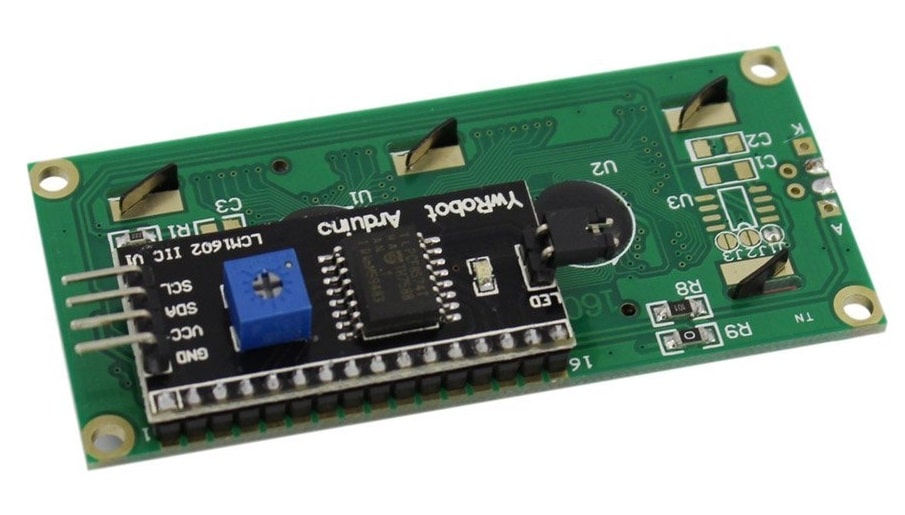
Connecting an LCD with an I2C backpack is pretty self-explanatory. Connect the SDA pin on the Pi to the SDA pin on the LCD, and the SCL pin on the Pi to the SCL pin on the LCD. The ground and Vcc pins will also need to be connected. Most LCDs can operate with 3.3V, but they’re meant to be run on 5V, so connect it to the 5V pin of the Pi if possible.
Connecting an LCD With a PCF8574
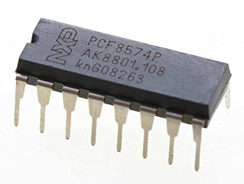
If you have an LCD without I2C and have a PCF8574 chip lying around, you can use it to connect your LCD with a little extra wiring. The PCF8574 is an 8 bit I/O expander which converts a parallel signal into I2C and vice-versa. The Raspberry Pi sends data to the PCF8574 via I2C. The PCF8574 then converts the I2C signal into a 4 bit parallel signal, which is relayed to the LCD.
Use the following diagram to connect the LCD to the Raspberry Pi via the PCF8574:
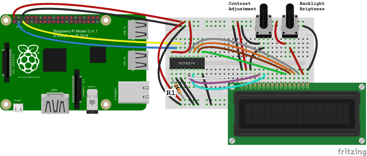
- R1: 10K Ohm resistor
- Potentiometers: 10K Ohms, but can be substituted with 1K to 3K Ohm resistors
In the diagram above, the blue wire connects to the Raspberry Pi’s SDA pin. The yellow wire connects to the Pi’s SCL pin.
Enable I2C on the Pi
Before we get into the programming, we need to make sure the I2C module is enabled on the Pi and install a couple tools that will make it easier to use I2C.
Enable I2C in raspi-config
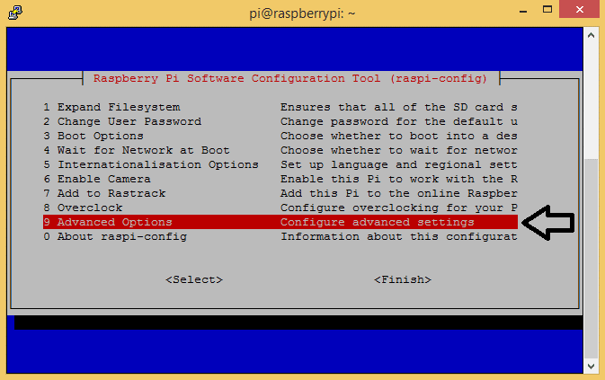
First, log in to your Pi and enter sudo raspi-config to access the configuration menu. Then arrow down and select “Advanced Settings”:
Now arrow down and select “I2C Enable/Disable automatic loading”:
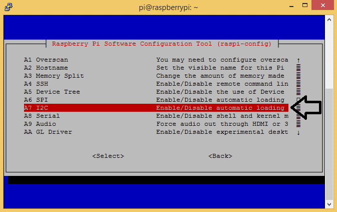
Choose “Yes” at the next prompt, exit the configuration menu, and reboot the Pi to activate the settings.
Install I2C-tools and SMBUS
Now we need to install a program called I2C-tools, which will tell us the I2C address of the LCD when it’s connected to the Pi. So at the command prompt, enter sudo apt-get install i2c-tools.
Next we need to install SMBUS, which gives the Python library we’re going to use access to the I2C bus on the Pi. At the command prompt, enter sudo apt-get install python-smbus.
Now reboot the Pi and log in again. With your LCD connected, enter i2cdetect -y 1 at the command prompt. This will show you a table of addresses for each I2C device connected to your Pi:
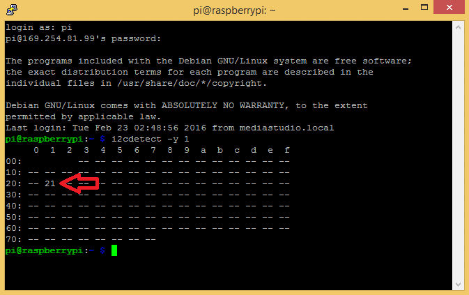
The I2C address of my LCD is 21. Take note of this number, we’ll need it later.
Programming the LCD
We’ll be using Python to program the LCD, so if this is your first time writing/running a Python program, you may want to check out How to Write and Run a Python Program on the Raspberry Pi before proceeding.
Installing the Library
I found a Python I2C library that has a good set of functions and works pretty well. This library was originally posted here, then expanded and improved by GitHub user DenisFromHR.
Copy this code for the library, then save it in a file named I2C_LCD_driver.py:
# -*- coding: utf-8 -*-
# Original code found at:
# https://gist.github.com/DenisFromHR/cc863375a6e19dce359d

"""
Compiled, mashed and generally mutilated 2014-2015 by Denis Pleic
Made available under GNU GENERAL PUBLIC LICENSE

# Modified Python I2C library for Raspberry Pi
# as found on http://www.recantha.co.uk/blog/?p=4849
# Joined existing 'i2c_lib.py' and 'lcddriver.py' into a single library
# added bits and pieces from various sources
# By DenisFromHR (Denis Pleic)
# 2015-02-10, ver 0.1

"""

# i2c bus (0 -- original Pi, 1 -- Rev 2 Pi)
I2CBUS = 0

# LCD Address
ADDRESS = 0x27

import smbus
from time import sleep

class i2c_device:
   def __init__(self, addr, port=I2CBUS):
      self.addr = addr
      self.bus = smbus.SMBus(port)

# Write a single command
   def write_cmd(self, cmd):
      self.bus.write_byte(self.addr, cmd)
      sleep(0.0001)

# Write a command and argument
   def write_cmd_arg(self, cmd, data):
      self.bus.write_byte_data(self.addr, cmd, data)
      sleep(0.0001)

# Write a block of data
   def write_block_data(self, cmd, data):
      self.bus.write_block_data(self.addr, cmd, data)
      sleep(0.0001)

# Read a single byte
   def read(self):
      return self.bus.read_byte(self.addr)

# Read
   def read_data(self, cmd):
      return self.bus.read_byte_data(self.addr, cmd)

# Read a block of data
   def read_block_data(self, cmd):
      return self.bus.read_block_data(self.addr, cmd)


# commands
LCD_CLEARDISPLAY = 0x01
LCD_RETURNHOME = 0x02
LCD_ENTRYMODESET = 0x04
LCD_DISPLAYCONTROL = 0x08
LCD_CURSORSHIFT = 0x10
LCD_FUNCTIONSET = 0x20
LCD_SETCGRAMADDR = 0x40
LCD_SETDDRAMADDR = 0x80

# flags for display entry mode
LCD_ENTRYRIGHT = 0x00
LCD_ENTRYLEFT = 0x02
LCD_ENTRYSHIFTINCREMENT = 0x01
LCD_ENTRYSHIFTDECREMENT = 0x00

# flags for display on/off control
LCD_DISPLAYON = 0x04
LCD_DISPLAYOFF = 0x00
LCD_CURSORON = 0x02
LCD_CURSOROFF = 0x00
LCD_BLINKON = 0x01
LCD_BLINKOFF = 0x00

# flags for display/cursor shift
LCD_DISPLAYMOVE = 0x08
LCD_CURSORMOVE = 0x00
LCD_MOVERIGHT = 0x04
LCD_MOVELEFT = 0x00

# flags for function set
LCD_8BITMODE = 0x10
LCD_4BITMODE = 0x00
LCD_2LINE = 0x08
LCD_1LINE = 0x00
LCD_5x10DOTS = 0x04
LCD_5x8DOTS = 0x00

# flags for backlight control
LCD_BACKLIGHT = 0x08
LCD_NOBACKLIGHT = 0x00

En = 0b00000100 # Enable bit
Rw = 0b00000010 # Read/Write bit
Rs = 0b00000001 # Register select bit

class lcd:
   #initializes objects and lcd
   def __init__(self):
      self.lcd_device = i2c_device(ADDRESS)

      self.lcd_write(0x03)
      self.lcd_write(0x03)
      self.lcd_write(0x03)
      self.lcd_write(0x02)

      self.lcd_write(LCD_FUNCTIONSET | LCD_2LINE | LCD_5x8DOTS | LCD_4BITMODE)
      self.lcd_write(LCD_DISPLAYCONTROL | LCD_DISPLAYON)
      self.lcd_write(LCD_CLEARDISPLAY)
      self.lcd_write(LCD_ENTRYMODESET | LCD_ENTRYLEFT)
      sleep(0.2)


   # clocks EN to latch command
   def lcd_strobe(self, data):
      self.lcd_device.write_cmd(data | En | LCD_BACKLIGHT)
      sleep(.0005)
      self.lcd_device.write_cmd(((data & ~En) | LCD_BACKLIGHT))
      sleep(.0001)

   def lcd_write_four_bits(self, data):
      self.lcd_device.write_cmd(data | LCD_BACKLIGHT)
      self.lcd_strobe(data)

   # write a command to lcd
   def lcd_write(self, cmd, mode=0):
      self.lcd_write_four_bits(mode | (cmd & 0xF0))
      self.lcd_write_four_bits(mode | ((cmd << 4) & 0xF0))

   # write a character to lcd (or character rom) 0x09: backlight | RS=DR<
   # works!
   def lcd_write_char(self, charvalue, mode=1):
      self.lcd_write_four_bits(mode | (charvalue & 0xF0))
      self.lcd_write_four_bits(mode | ((charvalue << 4) & 0xF0))

   # put string function with optional char positioning
   def lcd_display_string(self, string, line=1, pos=0):
    if line == 1:
      pos_new = pos
    elif line == 2:
      pos_new = 0x40 + pos
    elif line == 3:
      pos_new = 0x14 + pos
    elif line == 4:
      pos_new = 0x54 + pos

    self.lcd_write(0x80 + pos_new)

    for char in string:
      self.lcd_write(ord(char), Rs)

   # clear lcd and set to home
   def lcd_clear(self):
      self.lcd_write(LCD_CLEARDISPLAY)
      self.lcd_write(LCD_RETURNHOME)

   # define backlight on/off (lcd.backlight(1); off= lcd.backlight(0)
   def backlight(self, state): # for state, 1 = on, 0 = off
      if state == 1:
         self.lcd_device.write_cmd(LCD_BACKLIGHT)
      elif state == 0:
         self.lcd_device.write_cmd(LCD_NOBACKLIGHT)

   # add custom characters (0 - 7)
   def lcd_load_custom_chars(self, fontdata):
      self.lcd_write(0x40);
      for char in fontdata:
         for line in char:
            self.lcd_write_char(line)
There are a couple things you may need to change in the code above, depending on your set up. On line 19 there is a function that defines the port for the I2C bus (I2CBUS = 0). Older Raspberry Pi’s used port 0, but newer models use port 1. So depending on which RPi model you have, you might need to change this from 0 to 1.
Next, put the I2C address of your LCD in line 22 of the library code. For example, my I2C address is 21, so I’ll change line 22 to ADDRESS = 0x21.
Write to the Display
The following is a bare minimum “Hello World!” program to demonstrate how to initialize the LCD:
import I2C_LCD_driver
from time import *

mylcd = I2C_LCD_driver.lcd()

mylcd.lcd_display_string("Hello World!", 1)
Position the Text
The function mylcd.lcd_display_string() prints text to the screen and also lets you chose where to position it. The function is used as mylcd.lcd_display_string("TEXT TO PRINT", ROW, COLUMN). For example, the following code prints “Hello World!” to row 2, column 3:
import I2C_LCD_driver
from time import *

mylcd = I2C_LCD_driver.lcd()

mylcd.lcd_display_string("Hello World!", 2, 3)
On a 16×2 LCD, the rows are numbered 1 – 2, while the columns are numbered 0 – 15. So to print “Hello World!” at the first column of the top row, you would use mylcd.lcd_display_string("Hello World!", 1, 0).
Clear the Screen
The function mylcd.lcd_clear() clears the screen:
import I2C_LCD_driver
from time import *

mylcd = I2C_LCD_driver.lcd()

mylcd.lcd_display_string("This is how you", 1)
sleep(1)

mylcd.lcd_clear()

mylcd.lcd_display_string("clear the screen", 1)
sleep(1)

mylcd.lcd_clear()
Blinking Text
We can use a simple while loop with the mylcd.lcd_display_string() and mylcd.lcd_clear() functions to create a continuous blinking text effect:
import time
import I2C_LCD_driver
mylcd = I2C_LCD_driver.lcd()

while True:
    mylcd.lcd_display_string(u"Hello world!")
    time.sleep(1)
    mylcd.lcd_clear()
    time.sleep(1)
You can use the time.sleep() function on line 7 to change the time (in seconds) the text stays on. The time the text stays off can be changed in the time.sleep() function on line 9. To end the program, press Ctrl-C.
Print the Date and Time
The following program prints the current date and time to the LCD:
import I2C_LCD_driver
import time
mylcd = I2C_LCD_driver.lcd()


while True:
    mylcd.lcd_display_string("Time: %s" %time.strftime("%H:%M:%S"), 1)

    mylcd.lcd_display_string("Date: %s" %time.strftime("%m/%d/%Y"), 2)
Print Your IP Address
This code prints the IP address of your ethernet connection (eth0). To print the IP of your WiFi connection, change eth0 to wlan0 in line 18:
import I2C_LCD_driver
import socket
import fcntl
import struct

mylcd = I2C_LCD_driver.lcd()

def get_ip_address(ifname):
    s = socket.socket(socket.AF_INET, socket.SOCK_DGRAM)
    return socket.inet_ntoa(fcntl.ioctl(
        s.fileno(),
        0x8915,
        struct.pack('256s', ifname[:15])
    )[20:24])

mylcd.lcd_display_string("IP Address:", 1)

mylcd.lcd_display_string(get_ip_address('eth0'), 2)
Scroll Text Right to Left Continuously
This program will scroll a text string from the right side of the LCD to the left side and loop continuously:
import I2C_LCD_driver
from time import *

mylcd = I2C_LCD_driver.lcd()

str_pad = " " * 16
my_long_string = "This is a string that needs to scroll"
my_long_string = str_pad + my_long_string

while True:
    for i in range (0, len(my_long_string)):
        lcd_text = my_long_string[i:(i+16)]
        mylcd.lcd_display_string(lcd_text,1)
        sleep(0.4)
        mylcd.lcd_display_string(str_pad,1)
Scroll Text Right to Left Once
The following code slides text onto the screen from right to left once, then stops and leaves a cleared screen.
import I2C_LCD_driver
from time import *

mylcd = I2C_LCD_driver.lcd()

str_pad = " " * 16
my_long_string = "This is a string that needs to scroll"
my_long_string = str_pad + my_long_string

for i in range (0, len(my_long_string)):
 lcd_text = my_long_string[i:(i+16)]
 mylcd.lcd_display_string(lcd_text,1)
 sleep(0.4)
 mylcd.lcd_display_string(str_pad,1)
Scroll Text Left to Right Once
This program slides text onto the screen from left to right once, then stops and leaves the first 16 characters of the text string on the screen.
import I2C_LCD_driver
from time import *

mylcd = I2C_LCD_driver.lcd()

padding = " " * 16
my_long_string = "This is a string that needs to scroll"
padded_string = my_long_string + padding

for i in range (0, len(my_long_string)):
 lcd_text = padded_string[((len(my_long_string)-1)-i):-i]
 mylcd.lcd_display_string(lcd_text,1)
 sleep(0.4)
 mylcd.lcd_display_string(padding[(15+i):i], 1)
Custom Characters
You can create any pattern you want and print it to the display as a custom character. Each character is an array of 5 x 8 pixels. Up to 8 custom characters can be defined and stored in the LCD’s memory. This custom character generator will help you create the bit array needed to define the characters in the LCD memory.
Printing a Single Custom Character
The following code generates a “<” character:
import I2C_LCD_driver
from time import *

mylcd = I2C_LCD_driver.lcd()

fontdata1 = [
        [ 0b00010,
          0b00100,
          0b01000,
          0b10000,
          0b01000,
          0b00100,
          0b00010,
          0b00000 ],
]

mylcd.lcd_load_custom_chars(fontdata1)
mylcd.lcd_write(0x80)
mylcd.lcd_write_char(0)
Printing Multiple Custom Characters
This program prints a large right pointing arrow (→) to the screen:
import I2C_LCD_driver
from time import *

mylcd = I2C_LCD_driver.lcd()

fontdata1 = [
        # char(0) - Upper-left character
        [ 0b00000,
          0b00000,
          0b00000,
          0b00000,
          0b00000,
          0b00000,
          0b11111,
          0b11111 ],

        # char(1) - Upper-middle character
        [ 0b00000,
          0b00000,
          0b00100,
          0b00110,
          0b00111,
          0b00111,
          0b11111,
          0b11111 ],

        # char(2) - Upper-right character
        [ 0b00000,
          0b00000,
          0b00000,
          0b00000,
          0b00000,
          0b00000,
          0b10000,
          0b11000 ],

        # char(3) - Lower-left character
        [ 0b11111,
          0b11111,
          0b00000,
          0b00000,
          0b00000,
          0b00000,
          0b00000,
          0b00000 ],

        # char(4) - Lower-middle character
        [ 0b11111,
          0b11111,
          0b00111,
          0b00111,
          0b00110,
          0b00100,
          0b00000,
          0b00000 ],

        # char(5) - Lower-right character
        [ 0b11000,
          0b10000,
          0b00000,
          0b00000,
          0b00000,
          0b00000,
          0b00000,
          0b00000 ],
]

mylcd.lcd_load_custom_chars(fontdata1)

mylcd.lcd_write(0x80)
mylcd.lcd_write_char(0)
mylcd.lcd_write_char(1)
mylcd.lcd_write_char(2)

mylcd.lcd_write(0xC0)
mylcd.lcd_write_char(3)
mylcd.lcd_write_char(4)
mylcd.lcd_write_char(5)
Print Data from a Sensor
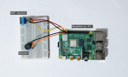
The code below will display data from a DHT11 temperature and humidity sensor. Follow this tutorial for instructions on how to set up the DHT11 on the Raspberry Pi. The DHT11 signal pin is connected to BCM pin 4 (physical pin 7 of the RPi).
Temperature is displayed on line 1, and humidity is displayed on line 2:
import RPi.GPIO as GPIO
import dht11
import I2C_LCD_driver

from time import *

mylcd = I2C_LCD_driver.lcd()

GPIO.setwarnings(False)
GPIO.setmode(GPIO.BCM)
GPIO.cleanup()

while True:

  instance = dht11.DHT11(pin = 4)
  result = instance.read()

# Uncomment for Fahrenheit:
# result.temperature = (result.temperature * 1.8) + 32

  if result.is_valid():
    mylcd.lcd_display_string("Temp: %d%s C" % (result.temperature, chr(223)), 1)
    mylcd.lcd_display_string("Humidity: %d %%" % result.humidity, 2)
For Fahrenheit, un-comment lines 18 and 19, and change the C to an F in line 22. You can also change the signal pin of the DHT11 input in line 15.
By inserting the variable from your sensor into the mylcd.lcd_display_string() function (line 22 in the code above) you can print the sensor data just like any other text string.
These programs are just basic examples of ways you can control text on your LCD. Try changing things around and combining the code to get some interesting effects. For example, you can make some fun animations by scrolling with custom characters. Don’t have enough screen space to output all of your sensor data? Just print and clear each reading for a couple seconds in a loop.
Let us know in the comments if you have any questions or trouble setting this up. Also leave a comment if you have any other ideas on how to get some cool effects, or just to share your project!


Thank you so much!! I’ve been playing with a couple of other bits of code all day trying to make them work, and all they would give me was seemingly random characters and behave differently at different times… Frustration levels now abating. Thanks again :)
Greate article! Helped me to connect chinese PCF8574 lcd backpack (blue one).
It doesn’t work on python 3. why do I make it to work on Python 3??
Did you change I2C bus 0 in line 20 of the driver to 1?
want to use Python3 , then change all unichr to chr in I2C_LCD_driver.py,
this is only a demo program now, the real driver is RPi_I2C_driver.py (line 34 has the i2c address)
import RPi_I2C_driver, time
mylcd = RPi_I2C_driver.lcd()
mylcd.lcd_display_string(“Python3 rocks…”,1)
time.sleep(3)
mylcd.lcd_clear()
mylcd.backlight(0)
Hi, I was wondering how to set the backlight off and then on? I tried different methods using the drivers, but none of them worked.
Try setting LCD_NOBACKLIGHT = 0x02 instead of 0x00
Great article. I’m a total novice to all this but managed to get my LCD display up and running without a glitch.
I would also like to figure out how to switch the backlight on and off. Any help would be greatly appreciated.
I figured it out. Kind of obvious, but it was late and had been a long day.
To turn the backlight on:
mylcd.backlight(1)
And to turn it off:
mylcd.backlight(0)
Awesome info. Will it hurt anything using the lcd without an i2c 3v to 5v converter? I have the sainsmart 20×4 which is made for Arduino i believe.
I have connected my HD44780 to RPi via I2C interface, downloaded smbus for python, copy&pasted python-code from this website and… nothing. I have 16 white rectangles on first line and nothing on second line (i have blue lcd with white digits). Good news is that LCD reacts with white rectangles when I run python code, if it is just connected to RPi there is only blue backlight.
Do you know what might be wrong? My LCD has 0x27 address from i2cdetect. I connected i2c to HD44780 with 16 wires, pin by pin (1–1, 2–2, 3–3, etc.)
Any ideas?
why 16 wires? if you use i2c you had to connect only ground,vcc,sda,scl on the i2c adapter of the screen..
By the way I had the same problem. White character, via python i’m able to turn on and off the backlight.
Hi kb06, What size resistors are you using for the contrast? It could be that the contrast resistor is too small, making the contrast too high. Also, does your LCD have an I2C backpack or are you using the PCF8574?
Us newbies that trawl the web looking for drivers etc really appreciate a well explained library that actually works. Like a pearl among the swill of junk code & bloatware, so lucid. Re a 3v3 Pi talking to a 5v PC8574: The iffy i2c signal here is when the Pi releases the lines for the various pullups to squabble over. According to the datasheet the 8574 min threshold for a rising edge is 70% or 3v5. The Pi has 1k8 internal pullups to 3v3 and the $1 ebay 8574 cards typically have 10k external pullups to 5v, the line therefore settle to ~3v6, enough to work without level shifters. And, if you’re squeamish about 0.1v headroom, surely you’d use a shottky diode in series with the plus side of the lcd supply rather than the inconvenience of level shifters?
How would the code be different when using a DHT22 sensor?
Great tutorial! but…
Does anybody know how to print a custom character at a certain location (column / row)?
Line 1 has addresses beginning 0x80
Line 2 addresses begin at 0xc0
Columns are numbered 0 to 15
The following code will scroll a character from left to right on line one
[code]
import RPi_I2C_driver
from time import *
mylcd = RPi_I2C_driver.lcd()
fontdata1 = [
[ 0b000000,
0b000000,
0b000000,
0b000000,
0b000000,
0b000000,
0b000000,
0b000000 ],
[ 0b00000,
0b00100,
0b01110,
0b11111,
0b01110,
0b00100,
0b00000,
0b00000 ]
]
mylcd.lcd_load_custom_chars(fontdata1)
for column in range(16):
addr=0x80
addr+=column
#print diamond symbol at line 1 column x
mylcd.lcd_write(addr)
mylcd.lcd_write_char(1)
sleep(0.5)
#blank it out
mylcd.lcd_write(addr)
mylcd.lcd_write_char(0)
[/code]
Here’s the mapping of a 2004 display. I guess it also applies for the 1602.
http://web.alfredstate.edu/weimandn/lcd/lcd_addressing/LCD-20×4-memory(b).gif
Actually these work for me:
http://3.bp.blogspot.com/-9cE3CFwQVM4/ViKBLK62kqI/AAAAAAAAALU/qTXzLfHeQ7o/s1600/20×4-lcd-cursor-address-table.bmp
Thank you, this has helped me greatly! Do you know how to alter the library to connect two I2C LCD displays?
import RPi_I2C_driver, time
mylcd0 = RPi_I2C_driver.lcd( ADDR = 0x27 )
mylcd0.lcd_display_string(“lcd on default address.”,1)
mylcd1 = RPi_I2C_driver.lcd( ADDR = 0x28 )
mylcd1.lcd_display_string(“lcd on custom address”,1)
time.sleep(3)
mylcd1.lcd_clear()
mylcd1.backlight(0)
time.sleep(3)
mylcd0.lcd_clear()
mylcd0.backlight(0)
but first change 2 lines in RPi_I2C_driver.py ( +/- line 25/26 )
def __init__(self, ADDR = 0x27 ):
self.lcd_device = i2c_device(ADDR)
(code not fully tested, driver changes work, use i2cdetect to find i2c address of second lcd)
change
class lcd:
#initializes objects and lcd
def __init__(self):
self.lcd_device = i2c_device(ADDRESS)
TO
class lcd:
#initializes objects and lcd
def __init__(self,indirizzo=ADDRESS):
self.lcd_device = i2c_device(indirizzo)
and then when you initialize the lcd
mylcd = I2C_LCD_driver.lcd()
TO
mylcd = I2C_LCD_driver.lcd(0x3c)
or
mylcd = I2C_LCD_driver.lcd()
if you want to use the default address
Excellent, thanks for the quick response, I’ll give it a try.
It’s working? someone checked? I try but it’s fail.
it’s working? Anyone checked or have another idea how to connect two I2C LCD displays?
thanks a lot for tutorial, may I ask – does anyone know if there is a simple way to display info from volumio 2.0 over mpdlcd? LCD 16*2 is connected to RPi3 via i2c and functions…thank you…
Ask Volumio if they want to implement the functionality or if they had API for use on external program to query for status.
ok I understand, and thanks for your answer.
My LCD is up and running but I’m looking for a sample ‘Hello World’ sample code in PERL. Does anybody know a source?
take a look at https://metacpan.org/pod/Device::SMBus.
From there you had to adapt the examples in python
Hello, i use mpd and output the information from mpc current to the display.
This is the command that i use it for output
title = os.popen(‘mpc current -f %title%’).read()
mylcd.lcd_display_string(title, 1)
it works fine but on the end of the string there is a bad character.
On the end of the string from titel there is a “\n” and this is the bad character on the lcd.
How i delete this sign in the output?
Sorry for my bad english
You can try title[:-1] or title.strip()
\n is the return carriage…strip will do the trick!
Thank you now it looks beautiful :-)
Glad I found this page, helpd me a lot with my internet radio. I have used the clock as the second line on my screen, but by haivng this clock running on there it makes the next and previous buttons unresponsive. Does anyone know how to solve this please?
We need the code! Perhaps you are inside a loop? try using threads or handlers for gpio.
Do I need to change or add something (lines 91-97 or anywhere else of the driver) for a 20×4 display?
It should work on a 20×4 LCD without any changes to the library code
Tested and works. Thanks.
Though I may need to insert a level converter, running the LCD from 3.3v on the Pi doesn’t give enough contrast straight-on, have to view from 20 degrees below straight-on to see it. Or should it be safe for the Pi to run the LCD from 5v without converting levels on SDA1/SCL1?
Oops, missed the comment in the article about connecting to “the 5V pin of the Pi if possible”, so I guess it is safe.
Beware, most other tutorials are clear on the fact that you should NOT plug 5v to raspberry GPIOs. So if LCD has its own 5v pullups, voltage adaptation is needed. Or a 3.3v LCD.
I get the following error on RasPi3
Traceback (most recent call last):
File “hello.py”, line 1, in
import I2C_LCD_driver
File “/home/pi/I2C_LCD_driver.py”, line 21
def __init__(self, addr, port=I2CBUS):
^
IndentationError: expected an indented block
Would you please provide me with a solution?
copy your full code.
import I2C_LCD_driver
from time import *
mylcd = I2C_LCD_driver.lcd()
mylcd.lcd_display_string(“Hello World!”, 1)
——————————————————————
I need the File “/home/pi/I2C_LCD_driver.py” where the error is located…
# -*- coding: utf-8 -*-
# Original code found at:
# https://gist.github.com/DenisFromHR/cc863375a6e19dce359d
“””
Compiled, mashed and generally mutilated 2014-2015 by Denis Pleic
Made available under GNU GENERAL PUBLIC LICENSE
# Modified Python I2C library for Raspberry Pi
# as found on http://www.recantha.co.uk/blog/?p=4849
# Joined existing ‘i2c_lib.py’ and ‘lcddriver.py’ into a single library
# added bits and pieces from various sources
# By DenisFromHR (Denis Pleic)
# 2015-02-10, ver 0.1
“””
# i2c bus (0 — original Pi, 1 — Rev 2 Pi)
I2CBUS = 0
# LCD Address
ADDRESS = 0x27
import smbus
from time import sleep
class i2c_device:
def __init__(self, addr, port=I2CBUS):
…
I have just changed I2CBUS = 0 to I2CBUS = 1
Hi guys! Thanks for this tuto. How can I stop the date and time script with another script? No ctrl+c. I need to stop that scrip when another script starts but I don’t know how to doit
http://lmgtfy.com/?q=linux+kill+other+script
http://askubuntu.com/questions/526886/stopping-a-running-script-though-another-script-file
Check out this python module that extends the functionality of the HD44780 controller:
https://github.com/IoannesBracciano/rpi-dots
That looks really cool, thanks for posting it
LCD doesn’t display the DHT11 values part but displays others like the “hello world”. It just prints the value on the terminal. Why is that?
Is there a way to display more that 8 custom characters? I’m running into problems when trying to.
Thanks for your post!! Very helpful. Is there anyway I can use a 4×4 matrix keypad to display characters on the lcd. Thanks in advance :)
While the scrolling scripts are working on their own, when I try to incorporate scrolling into my own script, I get an error:
File “/home/pi/Documents/InternetRadio/I2C_LCD_driver.py”, line 160, in lcd_display_string
self.lcd_write(ord(char), Rs)
TypeError: ord() expected string of length 1, but int found
Why does it work okay in the above script but not in mine? Why is it expecting string length 1 from me? (excerpt):
for i in range (0, len(currentstream)):
lcd_text = currentstream[i:(i+20)] # displayed substring width, 4×20 LCD
mylcd.lcd_display_string(lcd_text,1)
sleep(0.2)
mylcd.lcd_display_string(str_pad,1)
got a problem with last python script
PRINT DATA FROM A SENSOR
when I try to run it i got this error message :
python temp.py
Traceback (most recent call last):
File “temp.py”, line 2, in
import dht11
ImportError: No module named dht11
can some one help me with this ?
Ran into same problem today.
git clone https://github.com/szazo/DHT11_Python
Then copy dhy11.py to your directory where your files are from above. So dht11.py is in the same directory as I2C_LCD_driver.py For example,
cp /home/pi/project/DHT11_Python/dht11.py /home/project/dht11.py
Just thought I’d say this is a great tutorial, really covers all possible bases. 😁
hello
if I follow this steps, I can use this code in a lcd 20×4 ?
I use 20×4 LCD and work fine!
HI!
Work great!
Thankyou….
I try with two display , now i have I2C_LCD_driver.py and I2C_LCD_driver2.py with different address and in code
import I2C_LCD_driver
mylcd = I2C_LCD_driver.lcd()
import I2C_LCD_driver2
mylcd2 = I2C_LCD_driver2.lcd()
How can I add in I2C_LCD_driver.py two address for two display ?
I want to show display with 0x3f and 0x3D same information ?
import RPi_I2C_driver, time
text = “same information”
mylcd0 = RPi_I2C_driver.lcd( ADDR = 0x3f )
mylcd0.lcd_display_string(text,1)
mylcd1 = RPi_I2C_driver.lcd( ADDR = 0x3D )
mylcd1.lcd_display_string(text,1)
time.sleep(3)
mylcd1.lcd_clear()
mylcd1.backlight(0)
time.sleep(3)
mylcd0.lcd_clear()
mylcd0.backlight(0)
but first change 2 lines in RPi_I2C_driver.py ( +/- line 25/26 )
def __init__(self, ADDR = 0x27 ):
self.lcd_device = i2c_device(ADDR)
(code not fully tested, driver changes work, check your indents)
Thank you , I hope I understand, I will try
I am having an issue with my LCD16x2 connected via an I2C module to the pi – the first time I run lcd_display_string and lcd_clear, the display will correctly display and remove the text, however the second (and any further times) I run the script, it does not clear the output, rather text gets added to the end of the last text.
Does anyone know how to resolve this?
hallo im traying to use this scipt, whit an crius oled lcd display. but i dont get anything on the screen??
do i maybe mist something? does the module maybe have to paste into an specific folder, whit modules? or does the module have to be compiled first?
i only get this error!! ??
Traceback (most recent call last):
File “lcdtest2.py”, line 3, in
mylcd = I2C_LCD_driver.lcd()
File “/home/pi/lcd_test/I2C_LCD_driver.py”, line 111, in __init__
self.lcd_write(0x03)
File “/home/pi/lcd_test/I2C_LCD_driver.py”, line 136, in lcd_write
self.lcd_write_four_bits(mode | (cmd & 0xF0))
File “/home/pi/lcd_test/I2C_LCD_driver.py”, line 131, in lcd_write_four_bits
self.lcd_device.write_cmd(data | LCD_BACKLIGHT)
File “/home/pi/lcd_test/I2C_LCD_driver.py”, line 34, in write_cmd
self.bus.write_byte(self.addr, cmd)
IOError: [Errno 110] Connection timed out
thanks allready,. greetz,freedom
On the Raspberry Pi zero W in raspi-config Advanced settings I can’t find the I2C, SPI or Serial enables
Look under menu option 5 – Interfacing Options then you should see options P1 – P8. I2C is P5, SPI is P4, Serial is P6.
Shown above in the tutorial they’re in Advanced. Is this a difference on the Zero W or a change between Raspbian Jessie and Stretch? Either way it should be updated to mention both.
I’m still using jessie with most recent updates. It’s the same on my Zero W and Pi 2.
How do I implement my DHT22? What library is the best one to use?
hey guys, i tried to set up my i2c with my lcd but the problem is the string command doesn’t display on my lcd
i tried the backlight command and it works.
I had this problem. The i2c backpack has a variable resistor this adjusts the contrast. Write a program which displays a string on line one and immediately exits. Now with a small screw driver adjust that potentiometer. Hopefully the string is now on display.
Thanks very much for your work and Videos, its works a charm on Python 3
Can I use this library with 20*4 LCD display?
Very good tutorial!
Is it possible to write to the display with the backlight off?
If I use lcd_display_string(“String”), the backlight is always switched on, even if it was set to off before.
Any ideas?
Regards
Stefan
Another point: To switch the backlight of the display off, I use this snippet:
import I2C_LCD_driver
mylcd = I2C_LCD_driver.lcd()
mylcd.backlight(0)
The problem now is, if the display was illuminated, the backlight will be switched off as exspected, so far so good.
But, if it is already black, it gets switched on for one moment and gets switched off again. So during the instantiation of mylcd the light goes on. How can I prevent that?
Thank you very much. It all worked out perfectly.
Thanks very much you make very very happy this afternoon
I have followed this tutorial but still the i2c lcd does not work. I get an error that says it cant find the librabry. Which folder should it be saved to?
This excellent website definitely has all the info I
needed about this subject and didn’t know who to ask.
Hi, Fantastic tutorial, after reading so many this is the only one that i have understood and got working.
Having said that, how would I get text stings that are longer that 16 to scroll?
any help would be great.
Thanks
Hello, by turning on i2c in PI configuration, will it affect any other device connected to gpios?
Hi. Thanks for this! It help me a lot.
I want to know if maybe you have some tutorial for making a menu. Im searching in google, and not find anything yet.
I want to make a menu with this library and physicall buttons. (i know how to make the buttons.. but not the menu, how move trough the menu also.
Thanks!
I dont speak english.
I used this module to interface 2 displays using 1 Arduino Uno board to displaying LCD 16×2 , and graphical display interface the display but only one LCD was working is it possible using Arduino Uno board
Bonjour, comment adapter “PRINT DATA FROM A SENSOR” à un AM2302 branché sur un Pi GPIO#4 ? Merci.
Very clear tutorial. Thanks. Worked straight away, but the IP address script gives an error.
Line 15:
structpack(‘256s’, ifname[:15])
structerror: argument for ‘s’ must be a bytes object
Great article indeed. How to use the LCD with a multiplexer TCA9548A? How can I specify the multiplexer channel? Many thanks for your feedback.
Thank you I can finally turn backlight on / off :D
This was a great tutorial, thank you! I have my PI setup as a webserver just for experiments and was curios if you have any examples on how to display the server uptime on the LCD? Thank you in advance!
Great stuff.
Just my little contribution. About scrolling long lines: Here is some code to “rotate” instead of scrolling. The rotate left and right functions have been derived from the geeksforgeeks page (https://www.geeksforgeeks.org/string-slicing-python-rotate-string):
def rotate_str_left(input, d):
“””
return the input string rotated of d character to the left
“””
Lfirst = input[0: d]
Lsecond = input[d:]
return Lsecond + Lfirst
def rotate_str_right(input, d):
“””
return the input string rotated of d character to the right
“””
Rfirst = input[0: len(input) – d]
Rsecond = input[len(input) – d:]
return Rsecond + Rfirst
import lib.I2C_LCD_driver as I2C_LCD_driver
from time import sleep
my_lcd = I2C_LCD_driver.lcd()
str_pad = ” — ” # can be any other set of spaces and charcaters, just keep it as short as possible
long_string = “Logger listening @ 115200 baud on ttyUSB0”
long_string1 = long_string + str_pad
max_chars = 20 # I am using a 4 x 20 LCD
while True:
if len(long_string) <= max_chars:
line1_Text = long_string
my_lcd.lcd_display_string(line1_Text, 1)
else:
line1_Text = long_string1[:max_chars]
my_lcd.lcd_display_string(line1_Text, 1)
long_string1 = rotate_str_left(long_string1, 1)
it writes on line 1 of the LCD, long_string can be passed or read from a file. If long_string length stays within the 20 characters limit it'll be printed on the LCD as is, otherwise it will be rotated (instead of scrolled) left bound. The rotate_right can be used if you need to display in languages that read from right to left.
great tutorial, But I get an error when running the write to display script
In line 114 self.lcd_device.write_cmd(data l LCD_BACKLIGHT)
I get Attribute error: ‘lcd’ object has no attribute ‘lcd_device’
trace back are lines 119 and 139
how do I make the orange pi display my ip when I turn it on?
tnx
I was looking how to do this with a USB to I2C adapter from amazon (10 bucks) on a windows machine using C#. They have a dll you can download CH341DLL.DLL and CH341DLLA64.DLL. But I had no idea how to use it’s methods to do what I needed with an LCD screen. This post helped me tremendously by running using the I2C_LCD_driver.py on a le potato to understand how everything works.
Below (if it fits) is the C# class I made to do this.
public class I2C
{
public static UInt32 LCD_CLEARDISPLAY = 0x01;
public static UInt32 LCD_RETURNHOME = 0x02;
public static UInt32 LCD_ENTRYMODESET = 0x04;
public static UInt32 LCD_DISPLAYCONTROL = 0x08;
public static UInt32 LCD_CURSORSHIFT = 0x10;
public static UInt32 LCD_FUNCTIONSET = 0x20;
public static UInt32 LCD_SETCGRAMADDR = 0x40;
public static UInt32 LCD_SETDDRAMADDR = 0x80;
public static UInt32 LCD_ENTRYRIGHT = 0x00;
public static UInt32 LCD_ENTRYLEFT = 0x02;
public static UInt32 LCD_ENTRYSHIFTINCREMENT = 0x01;
public static UInt32 LCD_ENTRYSHIFTDECREMENT = 0x00;
public static UInt32 LCD_DISPLAYON = 0x04;
public static UInt32 LCD_DISPLAYOFF = 0x00;
public static UInt32 LCD_CURSORON = 0x02;
public static UInt32 LCD_CURSOROFF = 0x00;
public static UInt32 LCD_BLINKON = 0x01;
public static UInt32 LCD_BLINKOFF = 0x00;
public static UInt32 LCD_DISPLAYMOVE = 0x08;
public static UInt32 LCD_CURSORMOVE = 0x00;
public static UInt32 LCD_MOVERIGHT = 0x04;
public static UInt32 LCD_MOVELEFT = 0x00;
public static UInt32 LCD_8BITMODE = 0x10;
public static UInt32 LCD_4BITMODE = 0x00;
public static UInt32 LCD_2LINE = 0x08;
public static UInt32 LCD_1LINE = 0x00;
public static UInt32 LCD_5x10DOTS = 0x04;
public static UInt32 LCD_5x8DOTS = 0x00;
public static UInt32 LCD_BACKLIGHT = 0x08;
public static UInt32 LCD_NOBACKLIGHT = 0x00;
public static UInt32 En = 0b00000100;
public static UInt32 Rw = 0b00000010;
public static UInt32 Rs = 0b00000001;
[DllImport(“CH341DLLA64.DLL”, EntryPoint = “CH341OpenDevice”, CharSet = CharSet.Unicode, SetLastError = true)]
private static extern UInt32 OpenI2C(ulong iIndex);
[DllImport(“CH341DLLA64.DLL”, EntryPoint = “CH341CloseDevice”, CharSet = CharSet.Unicode, SetLastError = true)]
private static extern void CloseI2C(ulong iIndex);
[DllImport(“CH341DLLA64.DLL”, EntryPoint = “CH341WriteI2C”, CharSet = CharSet.Unicode, SetLastError = true)]
private static extern bool WriteI2C(ulong iIndex, UInt32 iDevice, UInt32 iAddr, UInt32 iByte);
[DllImport(“CH341DLLA64.DLL”, EntryPoint = “CH341ReadI2C”, CharSet = CharSet.Unicode, SetLastError = true)]
private static extern bool ReadI2C(ulong iIndex, UInt32 iDevice, UInt32 iAddr, out IntPtr oByte);
[DllImport(“CH341DLLA64.DLL”, EntryPoint = “CH341StreamI2C”, CharSet = CharSet.Unicode, SetLastError = true)]
private static extern bool StreamI2C(ulong iIndex, ulong iWriteLength, UInt32[]? iWriteBuffer, ulong iReadLength, out UInt32[] oReadBuffer);
[DllImport(“CH341DLLA64.DLL”, EntryPoint = “CH341Set_D5_D0”, CharSet = CharSet.Unicode, SetLastError = true)]
private static extern bool CH341Set_D5_D0(ulong iIndex, UInt32 iSetDirOut, UInt32 iSetDataOut);
[DllImport(“CH341DLLA64.DLL”, EntryPoint = “CH341SetOutput”, CharSet = CharSet.Unicode, SetLastError = true)]
private static extern bool CH341SetOutput(ulong iIndex, ulong iEnable, ulong iSetDirOut, ulong iSetDataOut);
public static void Clear()
{
Write(LCD_CLEARDISPLAY);
Write(LCD_RETURNHOME);
}
public static void Strobe(UInt32 data)
{
I2C.WriteI2C(0, 0x27, 0x10, data | En | LCD_BACKLIGHT);
Thread.Sleep(6);
I2C.WriteI2C(0, 0x27, 0x10, (data & ~En) | LCD_BACKLIGHT);
Thread.Sleep(2);
}
public static void Write_Bits(UInt32 data)
{
I2C.WriteI2C(0, 0x27, 0x10, data | LCD_BACKLIGHT);
Thread.Sleep(1);
Strobe(data);
}
public static void Write(UInt32 cmd, UInt32 mode = 0x00)
{
Write_Bits(mode | (cmd & 0xF0));
Write_Bits(mode | ((cmd << 4) & 0xF0));
}
public static void DisplayString(string s, UInt32 line = 0x01, UInt32 pos = 0)
{
var pos_new = pos;
if(line == 0x02)
{
pos_new = 0x40 + pos;
}
if (line == 0x03)
{
pos_new = 0x14 + pos;
}
if (line == 0x04)
{
pos_new = 0x54 + pos;
}
Write(0x80 + pos_new);
foreach(char c in s)
{
Write((UInt32)c, Rs);
}
}
public static void Init(ulong index)
{
OpenI2C(index);
I2C.Write(0x03);
I2C.Write(0x03);
I2C.Write(0x03);
I2C.Write(0x02);
I2C.Write(LCD_FUNCTIONSET | LCD_2LINE | LCD_5x8DOTS | LCD_4BITMODE);
I2C.Write(LCD_DISPLAYCONTROL | LCD_DISPLAYON);
I2C.Write(LCD_CLEARDISPLAY);
I2C.Write(LCD_ENTRYMODESET | LCD_ENTRYLEFT);
Thread.Sleep(200);
}
public static void Close(ulong index)
{
CloseI2C(index);
}
}