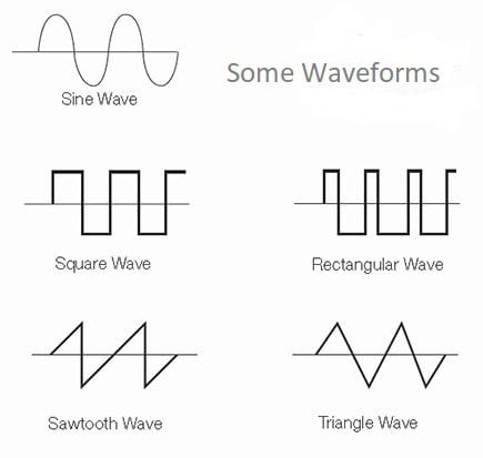
This is part three of a four-part tutorial series on wave generators and oscillators. Check out the other articles in this series: square wave generators, sawtooth and triangle wave generators, and crystal oscillators. In this article we will talk about sine waves and sine wave generators.

Sine waves, ideally, should contain no harmonics at all and are often used in signal generators used to test amplifiers and filters and radio frequency (RF) circuits to provide the carrier signals for receivers and transmitters. Spectral purity and stability are paramount. Although there are several ways to generate sine waves such as a digital source e.g. an Arduino, for this tutorial, we will look at three more common ways to do it.
Method 1: Wien Bridge Oscillators
Max Wien invented the Wien bridge oscillator in 1891. In 1939 under Frederick Terman’s guidance, two students at Stanford University, Hewlett and Packard, developed a working audio signal generator in their garage using a Wien bridge and a lamp stabilizer. This was their first product and the beginning of the Hewlett Packard company!
The circuit below is very much the same design except that it uses an op-amp instead of tubes (valves). It still uses the very suitable lamp amplitude regulator method.
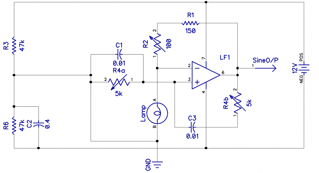
The bridge circuit is C1 R4a and C3 R4b. R4 is a dual-ganged potentiometer and controls the frequency, which is 1/2πRC. Assuming R4 is central, say 2k, this would be 1/(2*π* 5k * 0.01u) = 3kHz. The lamp is a small 12V incandescent light bulb. As the filament heats up, its resistance goes up, reducing the current through it, reducing the gain and amplitude at the output, so you have a very effective negative feedback amplitude control. The idea is to adjust R2 so that the circuit only goes into oscillation. This gives a smaller output but the best low distortion performance.
C1 R4a is a series or high-pass filter, and C3 R4b is a parallel low-pass filter. When they are the same at any given point, the positive feedback from the output to the non-inverting input causes the amp to oscillate at a gain set by 1+ R2/Rlamp.
As you can see from the Fourier display in the oscilloscope images below, the worst harmonic is 58dB down; this is about 0.13% THD. If you were to follow this circuit with a low pass filter set to cut just after the set frequency, you could knock another 30dB off, making it well below 0.01% assuming the filter doesn’t add too much distortion of its own.
If an oscillator is very clean, amplitude stable, and able to tune over a 10:1 frequency range, and with a selectable cap range, it makes a nice test oscillator. But a bigger value potentiometer would be better—I only had a 50k lying around. Note that the potentiometer should be linear and not logarithmic.
.
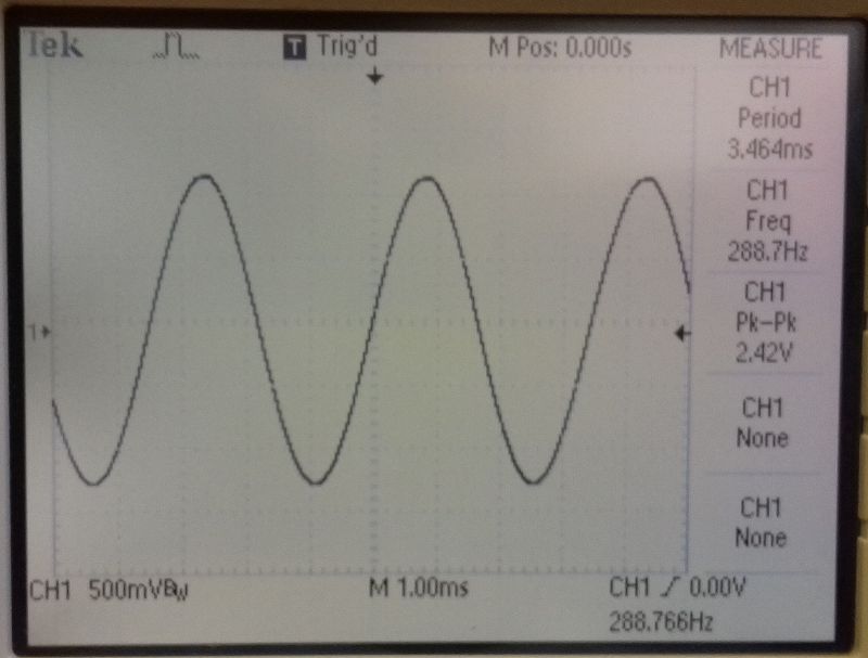 | 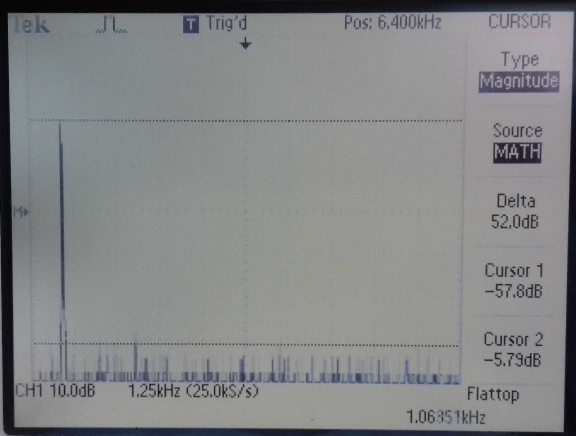 |
| A good clean sine wave | All harmonics > 58dB down |
Method 2: XR2206
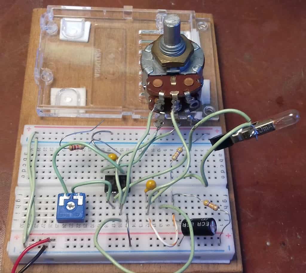
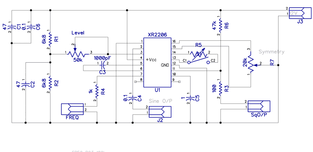
Another very convenient way to generate a good sine wave with a 10:1 tuning ratio is the XR2206 monolithic generator. This chip gives you a bonus of a square wave output that you can use to drive a frequency display. Adjusting R5 and R7 will set the THD to below 1%. Also, opening the switch on pin 13 will change the sine wave to a pretty good triangle wave shape.
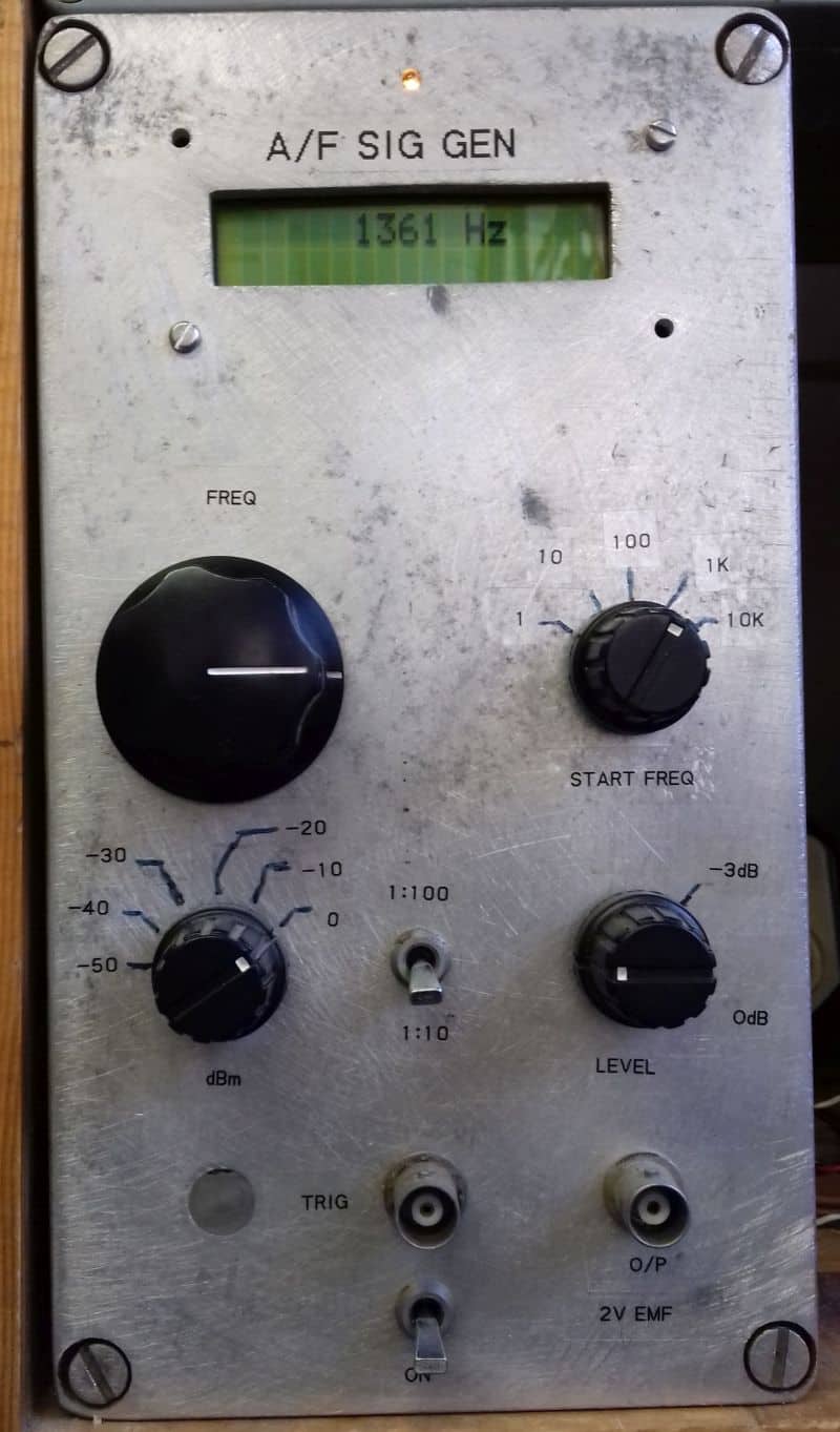
This oscillator will easily work from 10Hz to 100kHz, making a very nice bench audio signal generator or a full-fledged function generator. Combining two of these function generators and modulating the one with the other, just about any alarm sound or police/ambulance siren can be synthesized.
 | 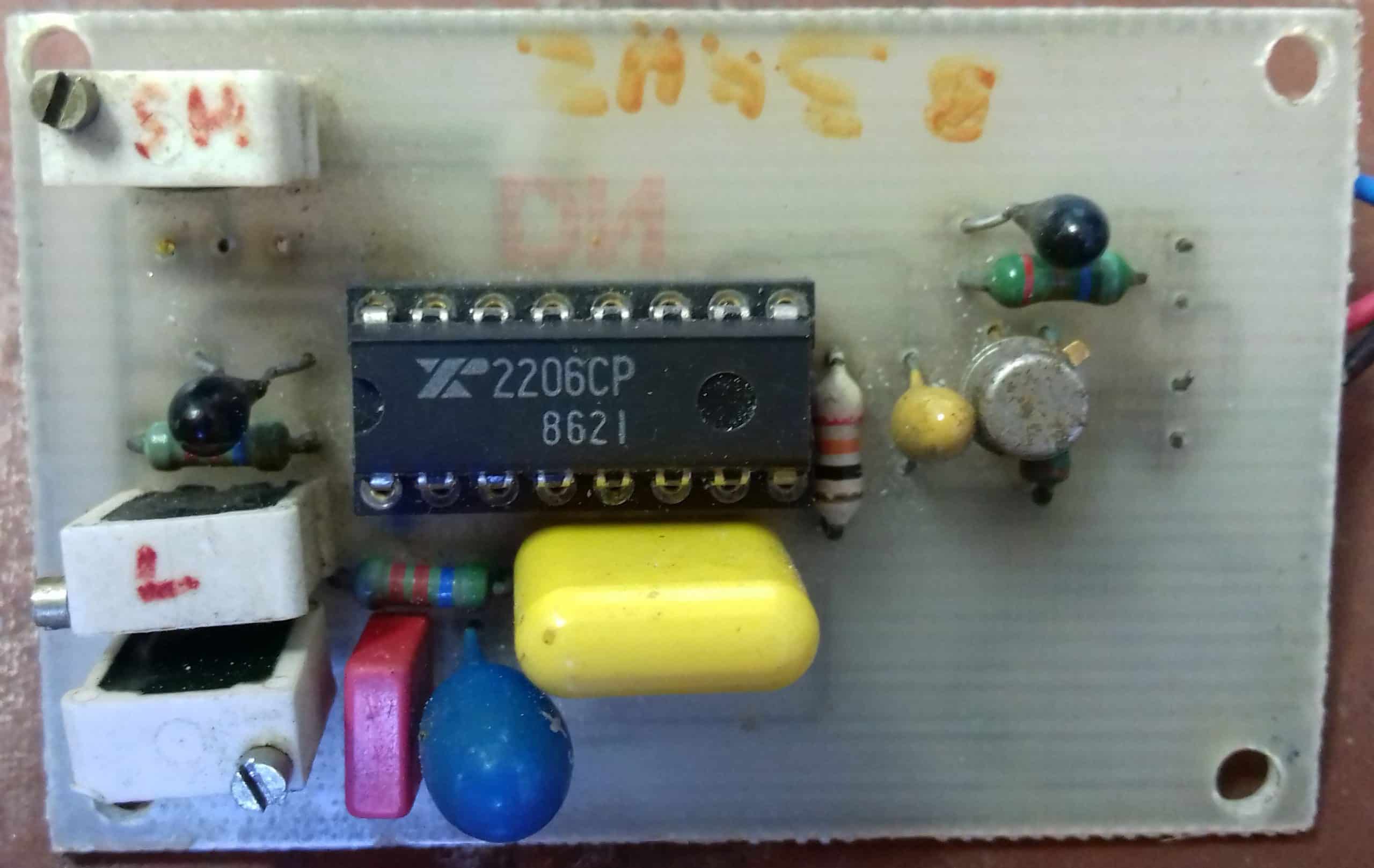 |
| A XR2206 audio oscillator | XR2206 PCB |
Method 3: Clapp Oscillator
If you need to have a sine wave at much higher frequencies than we can get with the Wien bridge and the XR2206, you need to go for an RF (radio frequency) type oscillator. Two prevalent types are Colpitts and Clapp, both of which use a tapped capacitor. Both are excellent choices. A slight variation of the Colpitts turns it into a Clapp oscillator.
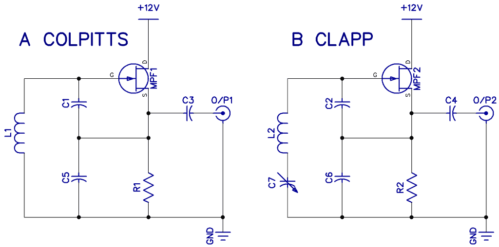
Diagram A shows a basic Colpitts. Note that C1 and C5 are in series/parallel with L1 and form the resonant circuit. In the Clapp shown in diagram B, the value of C7 is made much smaller than C2 and C6 and has a much larger effect on the tuning. If C7 is much smaller, frequency f is mostly dependent on C7 alone and more stable and tuned over a better range. This is why Clapp circuits are often the more popular choice for radio VFO’s (variable frequency oscillators).
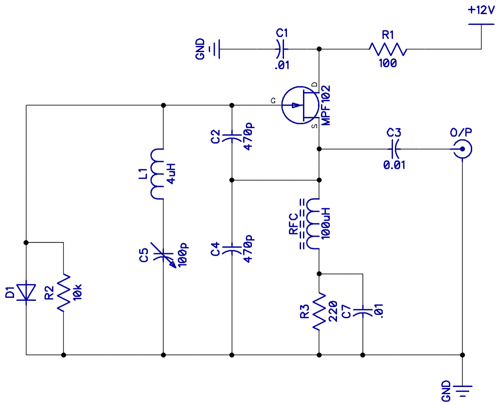
Shown below is a working Clapp VFO, and there are some interesting additions to the basic circuit. C1 R1 provides decoupling from the supply. RFC is about 10 turns of magnet wire on a ferrite ring, giving the source a higher impedance, and R3 provides bias to the FET. C2 and C4 are the main feedback caps, and C5 is the variable tuning capacitor. D1 R2 helps keep the amplitude down, making a better sine wave.
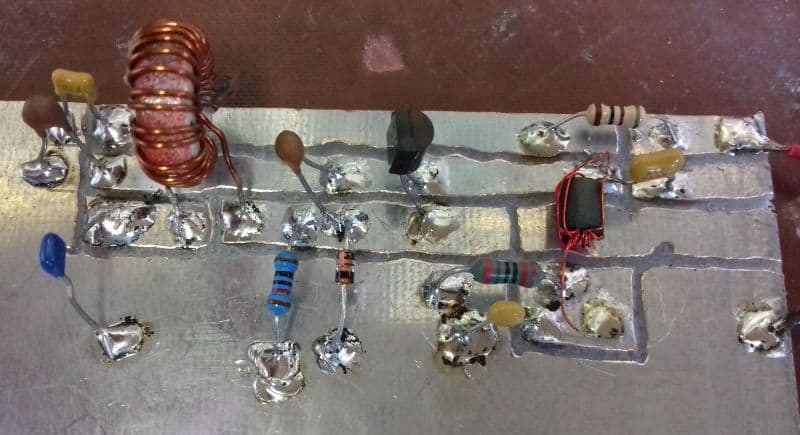
Below is the Clapp waveform of the circuit above, which is a good sine wave. Next to that is the Fourier display showing the second harmonic which is almost 40dB down (about 1% THD).
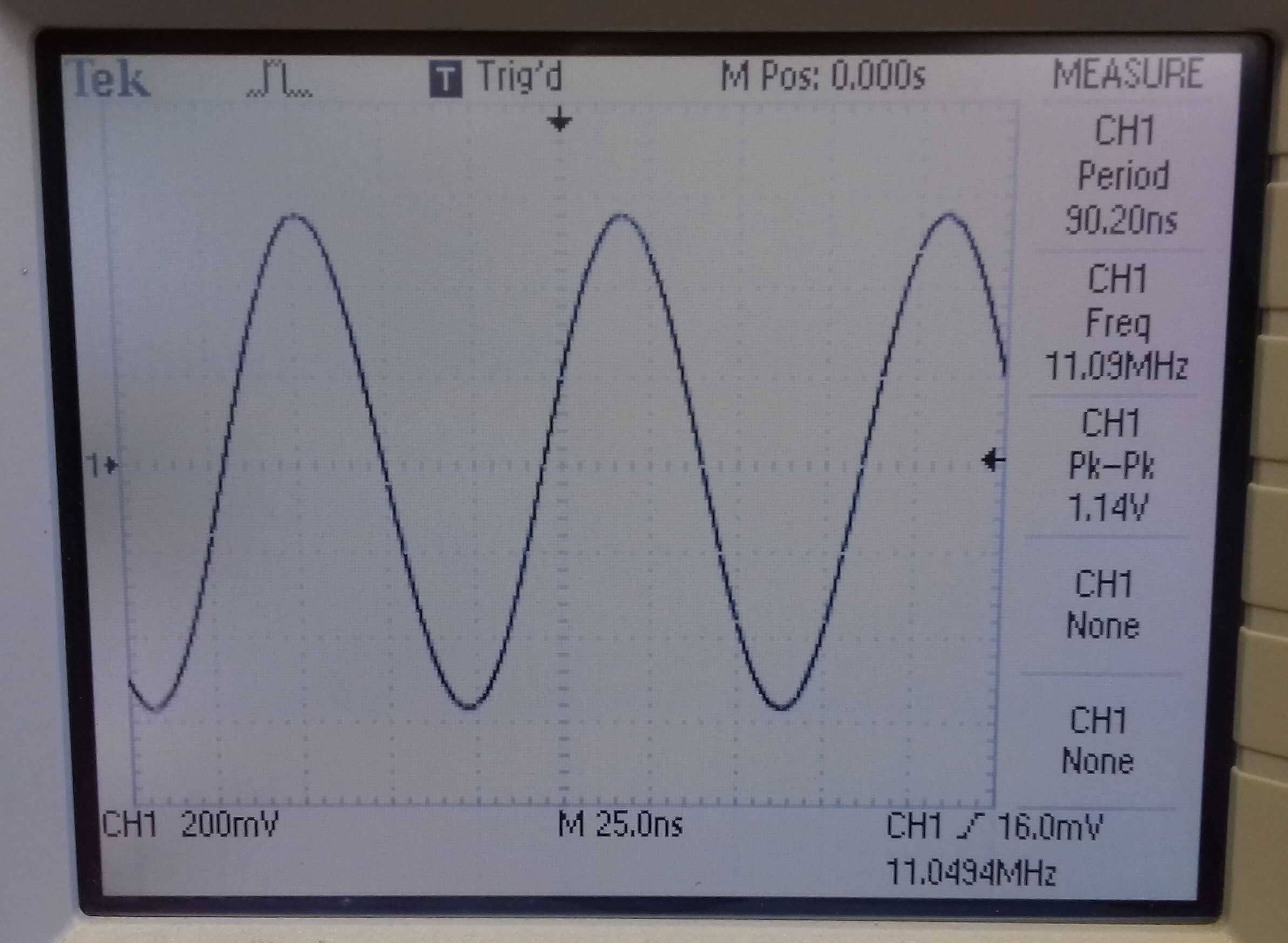 | 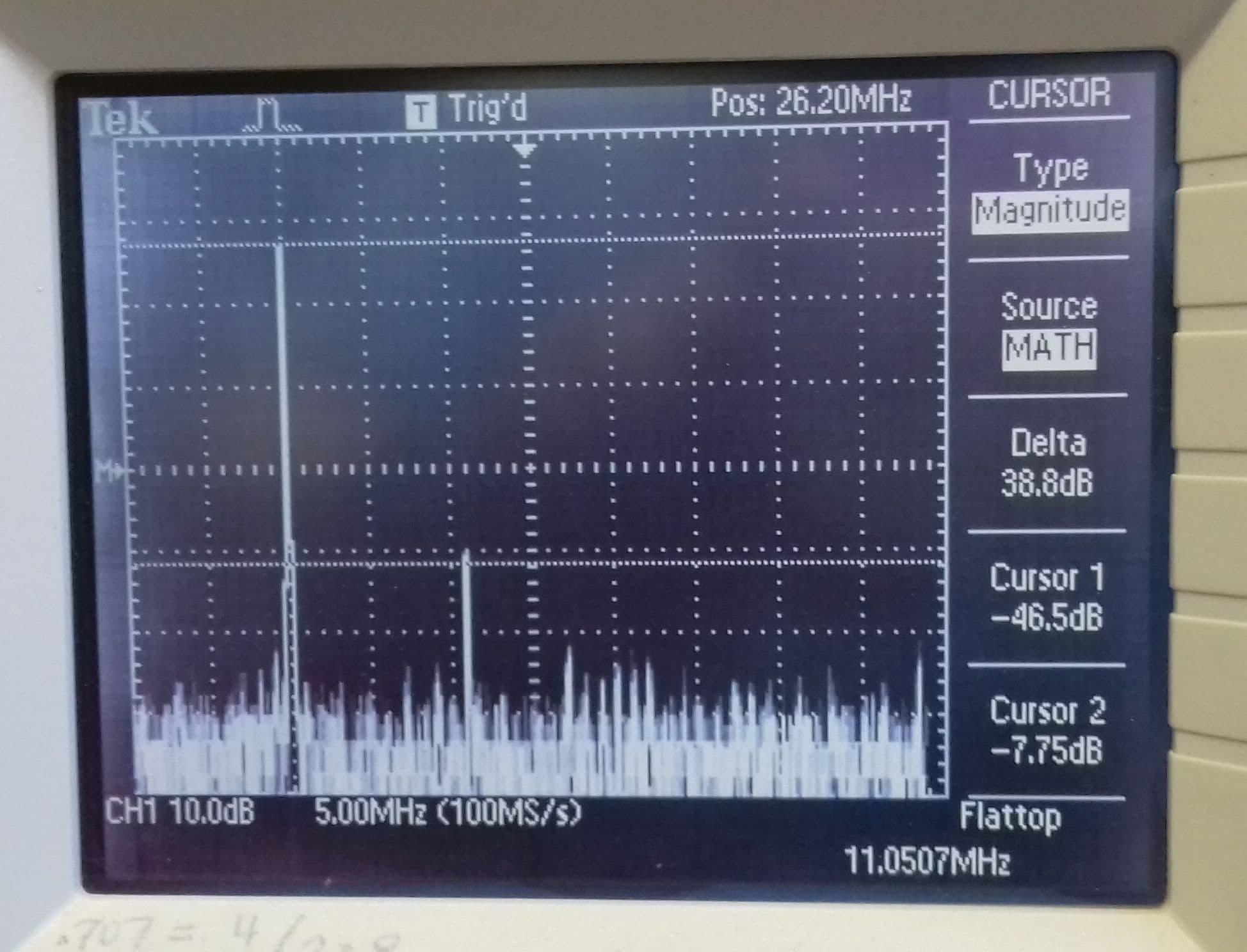 |
| Wave form of Clapp oscillator | Fourier display of Clapp oscillator 2nd harmonic is 1% |
Now, we have looked at four different sine wave oscillators, all giving nice clean waveforms. For the last article in this series, we will look at crystal oscillators. Be sure to leave a comment below if you have any questions!

I am thrilled by your pcb design! I adopted this more than forty years ago, (funds lacking) and still using it in 2021!! Great job regarding your tutorials, useful also a reminder to old timers like me! Keep up the good work and thank you! Oscar
thank you for sharing
Hello There. I found your blog using msn. This is a very well written article. I’ll be sure to bookmark it and return to read more of your useful information. Thanks for the post. I will certainly return.