In this article, we will learn about the built-in memory blocks of the Arduino prototyping platform. We will give particular emphasis on describing and understanding the basic operations of the different memory blocks on the Arduino, namely Flash Memory, Electrically Erasable Programmable Read-Only Memory (EEPROM) and Static Random Access Memory (SRAM). We will also discuss the architecture and physical design of memory.

What is Memory?
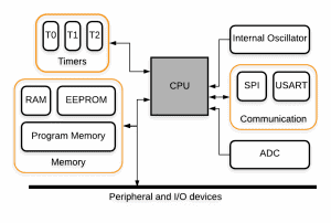
Memory is an essential resource important to any computing system, especially in embedded systems. The memory sub-system is one of the many sub-systems inside a microcontroller. In Figure 1, a bus connects the memory module to the CPU and I/O devices. The purpose of the memory block is to store run-time data or information temporarily or permanently, depending on the program requirements.
In the context of computing systems, memory refers to the metal-oxide-semiconductor devices which store and retrieve information or data for further processing by the CPU. We can consider memory as a tabular array of cells as shown in the diagram below. Each cell stores this information in the form of basic units called bits, which switch states between 0 and 1.
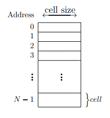
The cells have the following properties:
- Each cell can remember data of certain sizes. Typically, sizes of 1 byte or 8 bits of information can be stored in a cell.
- Each cell has a unique number for identification and location addressing.
- More importantly, we can store or read information from each cell through a WRITE or READ operation.
Memory Operations
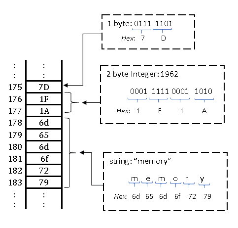
A write operation accepts an address and a value. A read operation accepts an address and returns the information stored at that particular location. Data storage – in some texts, the hexadecimal notation represents data in memory. The main advantage is that hex notation stores data more efficiently than integers or strings. For example, the hex notation of 01111101 is 7D, this value is then stored in a cell whose address is 175. Here, we see that each byte of memory is equivalent to two hex digits only. In another example, the memory storage for the decimal number 1962 is 1F1A. This requires only 2 memory cells for storage. We can repeat the same operation for storing a string such as “memory”.
Volatile vs Non-volatile Memory
There are different types of memory devices available, and the application area of each memory device depends on the architecture of the memory system.
Some memory systems require power to maintain the stored information. Such a system is called volatile memory. The device keeps the data as long as there is electrical power. This means that such short-term memory systems are suitable for storing working data and machine code.
On the other hand, some memory systems can remember the information even if the power of the device has been turned off. These are called non-volatile memory. The purpose of such memory systems is for long term data storage. Examples of non-volatile memory are ROM and flash memory.
Now, let’s see the difference between volatile and non-volatile memory:
| Volatile Memory | Non-Volatile Memory | |
| Description | Loses all the data when power is lost | Retains all the data when power cycled |
| Uses | Cache, Registers, Static RAM (SRAM), Dynamic RAM (DRAM) | Hard disk drives EEPROM Flash memory |
| Temporary retention of data | Permanent retention of information |
Types of Built-In Memory on the Arduino
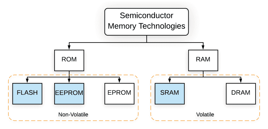
Figure 3 shows the general memory tree of a computer system. The diagram also shows the Arduino related memory sub-systems.
What is Flash Memory?
Flash memory, also known as flash storage, is the current leader in the semiconductor memory market in terms of both production units and sales. This is because flash memory has the lowest cost per bit memory. Also, it is fast and easy to store information. It is a non-volatile memory, which means that the cells keep the information for an extended period even when power to the device has been interrupted. In microcontroller chips, flash memory is integrated on-chip and it is used as program memory. Flash memory cells are electrically written or erased and they can have up to 10,000 write-erase cycles.
Flash memory is common in the following devices:
- Cell phones
- Computer networking devices
- Consumer electronic products such as digital cameras, camcorders, and video game consoles,
- Industrial devices, e.g. security systems, military systems, and retail products
- Memory cards and solid-state disk drives
How Flash Memory Works
For us to understand the working principles of a flash memory cell, we need to understand the operation of a basic floating-gate Metal Oxide Semiconductor Field Effect Transistor or MOSFET as shown in Figure 4.
A flash memory cell, in Figure 4b, uses the concept of a floating gate MOSFET to save a bit of information. The MOSFET has a control gate and a floating gate. The purpose of a dielectric material is to separate the control gate and the floating gate from the substrate and terminals. The floating gate is responsible for storing the charge as well as controlling the flow of current.
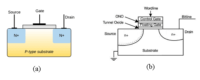
A MOSFET is a voltage-driven switch that controls the flow of current in an electronic circuit. The devices are made from a doped semiconductor material. Unlike magnetic power control devices, MOSFETs have a very small form factor and they do not have moving parts. This means that MOSFETs can operate much faster than magnetic switching devices. As shown in Figure 4, the devices have three basic external connections: the source, drain and the gate. The source is connected to the ground, the drain is connected to the load and finally, the MOSFET will be switched ON when a positive voltage is connected to the gate.
Flash Memory Cell
The charge of the floating gate determines the flow of current from the source to the drain. The floating gate can be neutral, positive or negatively charged. If the floating gate is neutral, then the storage transistor will behave like a normal MOSFET. A positive charge on the control gate creates a conducting channel in the p-substrate and current flows from the source to the drain. Lastly, a negative charge on the floating gate prevents the formation of a channel in the p-substrate.
Another important parameter is the threshold voltage. This is the minimum voltage at the control gate which can make the channel conductive.
Operations which can be performed on the flash memory cell include programming the cell and erasing the cell. When we program a Flash memory cell, what we are physically doing is placing electrons into the floating gate. On the other hand, when we remove the charge from the floating gate, we are essentially erasing the memory cell. However, the detailed process of trapping or removing electrons from the floating gate is beyond the scope of this article.
Arduino Flash Memory
Flash memory, also known as program memory, is where the Arduino stores and runs the sketch. Since the flash memory is non-volatile, the Arduino sketch is retrieved when the micro-controller is power cycled. However, once the sketch starts running, the data in the flash memory can no longer be changed. Modification can only be done when the program is copied into SRAM memory.
The table below show the amount of flash memory available on some different Arduino boards:
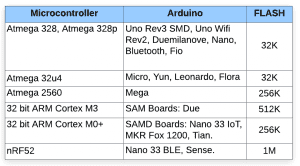
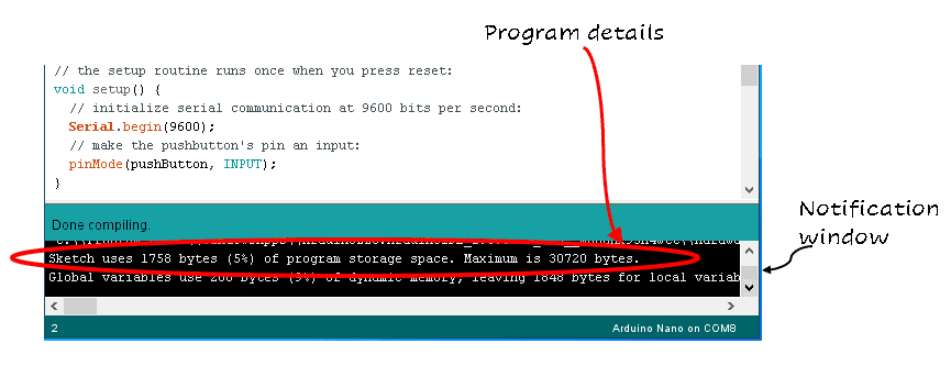
The size of the program is displayed after you upload the sketch in the program notification window at the bottom of the IDE. For this example, our code will only occupy 1758 bytes of program space from a total of 30720 bytes.
What is EEPROM Memory?
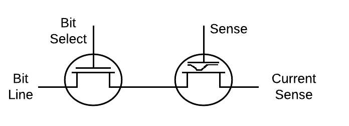
Electrically Erasable Programmable Read-Only Memory (EEPROM) is an inexpensive, non-volatile memory block which means that we do not lose the data when we remove power from the device. This type of memory is used to store small amounts of data which are written occasionally and then read multiple times. Most EEPROMs on the market today have either SPI or 12C serial interface for communication. An EEPROM memory cell is almost identical in architecture to the Flash memory cell, except that the EEPROM cell carries an additional regular CMOS transistor, as shown in Figure 6. The operation of a Flash memory cell and the trapping of charge by the floating gate have been discussed in the previous chapter. However, the additional transistor in the EEPROM structure is used to erase the charge.
Arduino EEPROM
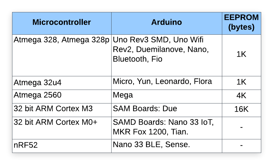
In some instances, we may need to store the states of certain input and output devices on the Arduino for long periods. For that, we save the data to EEPROM memory with the help of Arduino libraries or third-party EEPROM libraries. This helps us to remember the information when we power up the Arduino again. Most of the Arduino boards have built-in EEPROM memory, but in some cases, certain programs may require the use of an external EEPROM. The functions below help us to interact with the Arduino EEPROM.
#include <EEPROM.h>
EEPROM.write(address, value);
EEPROM.read(address);
EEPROM.update(address, value);
EEPROM.get(address);
EEPROM.put(address, value);
To update or write to EEPROM, we need the address to write to and also the value to write or update. The read function accepts the address to read from and returns the value stored at that address. The get() and put() functions operate just like the read() and write() functions respectively, except that the former allow us to store other data types such as floats, structs or integers.
What is SRAM Memory?
Static Random Access Memory (SRAM) is a type of RAM that uses a set of transistors to store a bit of data. SRAM memory is volatile. This means that the memory cell will hold a bit of data for as long as there is power to the circuit. Unlike Dynamic Random Access Memory (DRAM), the SRAM memory cell does not require constant refreshing to retain the data. It is much more expensive than DRAM, smaller in structure but faster. These characteristics are suitable for use in high-performance servers or cache memory, typically applied between the main memory and a system’s CPU.
How SRAM Memory Works
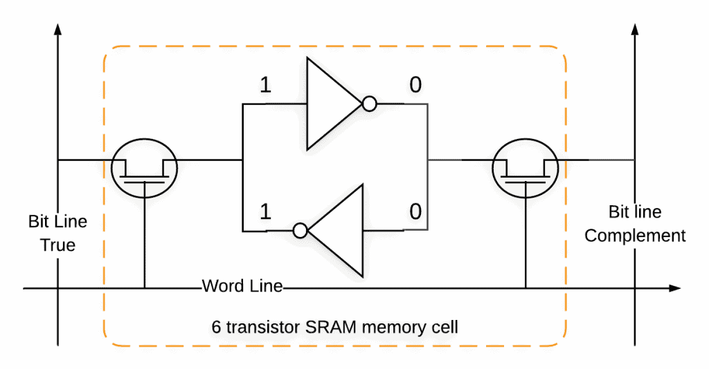
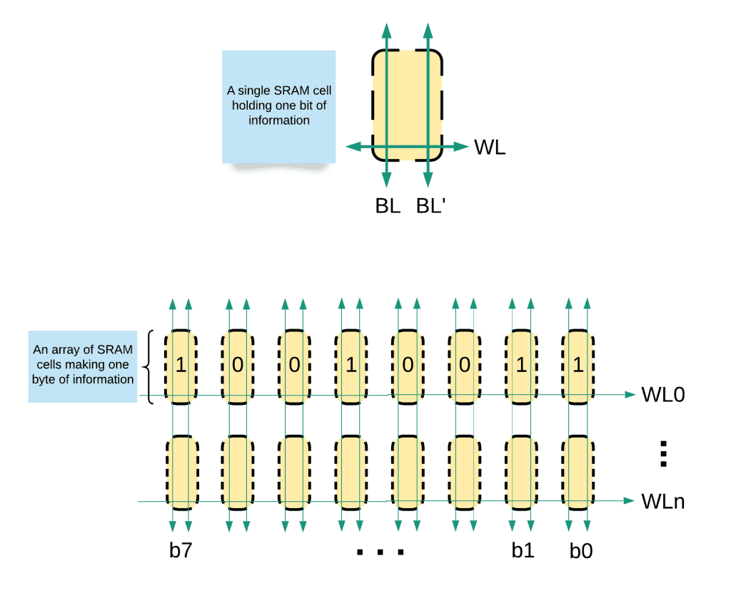
Figure 7 shows a typical SRAM memory cell for storing 1 bit of data. Multiple cells are stacked together in rows and columns to make a byte or words of memory, as shown in Figure 8. In the simplified SRAM representation which is shown in Figure 7, we see two inverted transistors which feedback on each other, bit lines, and a word line for addressing memory cell connection to the CPU. To write a byte of information, the address bytes are decoded so that the word line turns on the two transistors which correspond to this memory cell. Then, the bit lines are driven with the information to be stored. The inverted transistors which are inside the memory cell change their bit states to keep the new value. After a successful write operation, the word line is then turned off and the information is saved.
To read a value stored in SRAM memory, the address bytes are decoded to enable the word line which corresponds to the memory cells. When reading the data, nothing is driving the bit lines so the feedback inverters drive the saved data back to the bit lines instead.
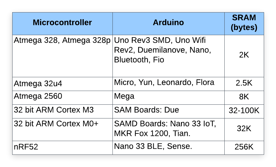
Arduino SRAM
The Arduino SRAM or runtime data is where the program creates and stores sub-routine variables and interrupts calls when the sketch runs. The initialized variables of a program are placed in the .data section while the uninitialized variables are placed in the .bss section. At the end of the SRAM block is where you find the stack. This is where the data that is created during the execution of function calls and interrupts are stored.

The size of the stack increases as the number of interruptions or variables increase. A healthy SRAM is something that has a lot of free memory, as shown in Figure 9a. As the stack grows, free memory becomes depleted and problems related to program execution may occur. Optimizing SRAM in an Arduino is subject of future works.
What happens if you run out of memory?
Improperly programmed Arduinos may run out memory during program execution. Figure 9b shows a stack that has grown to take up most of the free space of the SRAM block. When the Arduino runs out of memory (FLASH, SRAM and EEPROM), the following may occur:
- For Flash memory or SRAM: these are the most common and difficult to diagnose. The following can occur if SRAM runs out on the Arduino:
– The program can fail to execute or it can operate unexpectedly;
– Corruption of the program or variables yielding unpredictable results;
– When the stack fails, it will cause an immediate crash.
– If the program size is larger than the memory, the sketch may fail to upload. - EEPROM: Running out of EEPROM memory is a bit difficult since most programs hardly use EEPROM. If this happens, however, the operation of the main program will not be affected.
We will discuss the techniques to accommodate the peculiarities of built-in memory sub-systems on the Arduino in a future article. Please leave a comment below if you have a question.
References:
[1] https://www.creeaza.com/referate/informatica/calculatoare/Memoria-Flash-Principiile-de-f762.php