
In this tutorial, we will explore how the Raspberry Pi can be used to read analog signal data accurately and the use of potentiometers in carrying out this great task. Let’s get started!

One thing to note about the Raspberry Pi is that it is unable to read analog signals directly. It can detect digital signals like the push of a button or a simple change in a digital sensor’s state, but not the changes made by an analog sensor. But the good thing, there are two ways to actually sort this problem out.
The first method is to use an ADC (Analog-to-Digital Converter) like the MCP3008 (for 8 channels of analog input) or ADS1115 (for 4 channels of analog input). The only difference between them is that ADS1115 is better in precision compared to the MCP3008.
Fortunately, there’s another way to read the analog signals without having to buy an ADC chip. This saves us from the hassle of spending a lot on expensive chips. This method is known as “step-response.” Using this methodology, we see how the circuit behaves during a change in state from high to low or low to high, also known as ‘step change.’ This is done by using the charging and discharging circuit controlled by a potentiometer with a Raspberry Pi.
Now, let’s dive into that.
What is a Potentiometer?
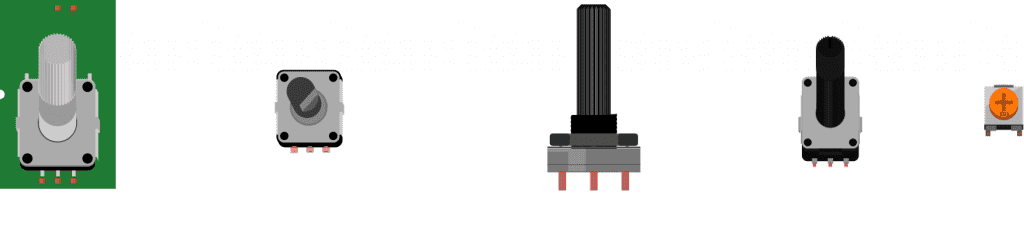
A potentiometer is a variable resistor used to vary the resistance in a circuit by rotating a knob. This is used to vary voltages in any circuit or to control current flow in a circuit. It contains three pins; the first one is used as an input and the second is for ground connection, and the third is situated in the corner as the output pin.
Reading Analog Signal Data with a Potentiometer
Now let’s build an example project that uses the Raspberry Pi to detect the analog signal generated by a potentiometer. We are using a potentiometer here as a simple example. The same principals can be applied to any other sensor that outputs an analog signal!
These are the components needed to build this project:
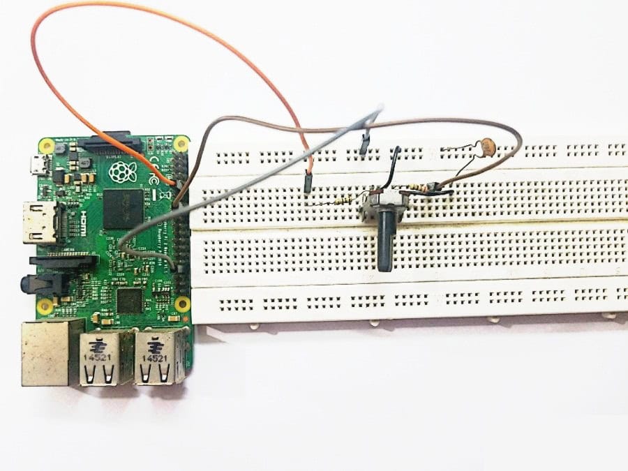
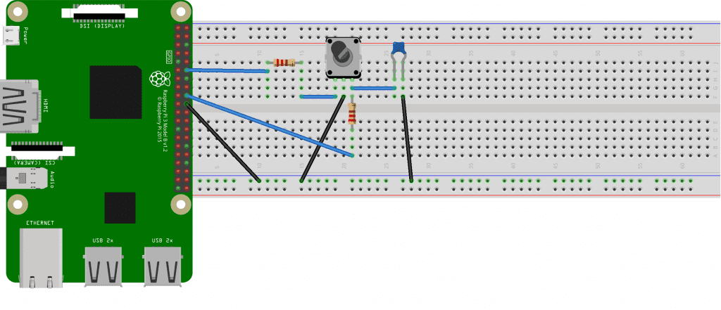
Once you have all of the parts, connect everything to the Raspberry Pi following this wiring diagram:
Before we proceed, let me explain something more clearly.
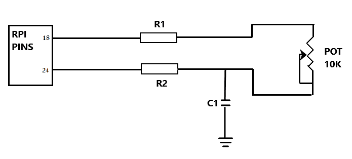
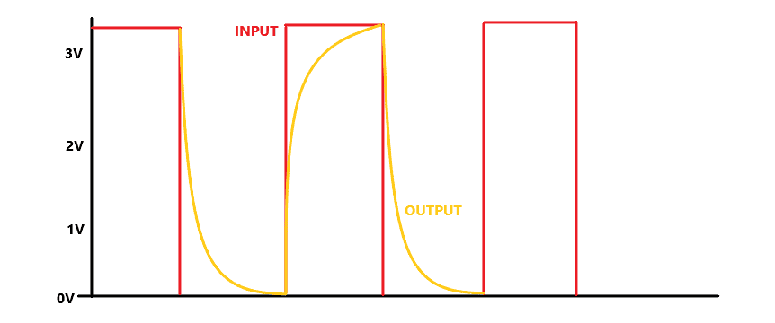
This entire circuitry depends on the charging and discharging of a capacitor, which, in turn, depends on how this circuit responds to an electrical pulse within a particular period of time. So, we particularly target the time to detect the analog signal value. This time is dependent on the variable resistance of the resistor, which we will change. All of these will be shown in the Raspberry Pi terminal.
In simple terms, the capacitor acts like a container of charge. As it fills with charge, the voltage across it rises, but you cannot read the voltage as Raspberry Pi is incapable of reading analog voltage value. Thus, to read this value, we basically note the time it takes for the voltage to go above 1.5-1.6V, typically a value that registers a digital high. The charging speed depends upon the value of the variable resistor; the less the value, the faster the capacitor will charge.
The second most important step to note here is that the capacitor needs to discharge completely before being used again to get a good reading. So for this, we use the resistor R1 connected to pin 18 with the 10K variable resistor for completely charging the capacitor. On the other hand, we use R2 for discharging the capacitor connected to pin 24 in Raspberry Pi.
We will now apply the step-response signal for 4 to 5 ms (well, generally 5ms). In that particular time, the capacitor will charge via R1 and variable resistor and will discharge via R2. The discharge time here is set to less than 1 ms and is done via the python code shown below. As this cycle continues for charging and discharging, the code acts as a counter and provides values equivalent to the step-response read by the Raspberry Pi. This is how the Raspberry Pi reads the entire analog signal with a potentiometer’s help in a step-response circuit.
In summary, we basically use R1 and the potentiometer to charge the circuit together, and R2 to discharge the circuit which is then read by the python code to give us the values for the step-response change with time.
Python Code for Reading a Potentiometer
After building the circuit, copy the code below to a text editor in the Raspberry Pi terminal and save it as a file named “step-res.py”.
import RPi.GPIO as GPIO
import time

GPIO.setmode(GPIO.BCM)

pin_a = 18
pin_b = 24

def discharge():
    GPIO.setup(pin_a, GPIO.IN)
    GPIO.setup(pin_b, GPIO.OUT)
    GPIO.output(pin_b, False)
    time.sleep(0.004)

def charge_time():
    GPIO.setup(pin_b, GPIO.IN)
    GPIO.setup(pin_a, GPIO.OUT)
    count = 0
    GPIO.output(pin_a, True)
    while not GPIO.input(b_pin):
        count = count + 1
    return count

def analog_read():
    discharge()
    return charge_time()

while True:
    print(analog_read())
    time.sleep(1)
Run the code by typing the following command in the terminal:
sudo python step-res.pyTerminal Response
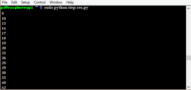
After running the code, you will start seeing the response in the terminal like the one shown above. As you rotate the potentiometer, the value will increase in one direction and decrease in the other.
This is the best possible method to read analog signals of any sensor. Just note that we did the step-response technique instead of using physical analog to digital converters. If you have the resources, it’s better to use a hardware ADC with the Raspberry Pi as they are easier to use and more accurate than the method above.
Thanks for reading and leave a comment below if you have questions about anything!


NOT WORKING MAN… AND BY THE WAY THERE IS AN ERROR.
PLEASE CORRECT OR REMOVE THIS ONE.
File “./potenzieometer.py”, line 7
pin-a = 18
^
SyntaxError: can’t assign to operator
THIS ONE IS NOT A PROBLEM. FIXED.
BUT THIS IS THE OUTPUT:
zoe@rasp-01:~/work/tmp/$ ./potenzieometer.py
./potenzieometer.py:11: RuntimeWarning: This channel is already in use, continuing anyway. Use GPIO.setwarnings(False) to disable warnings.
GPIO.setup(pina, GPIO.IN)
187
10439693
5410695
960996
You should rename the variables “pin-a” and “pin-b” as this way of declaring a variable is illegal/invalid due to “-” being an operand (- [minus]). Try updating the variable to “pin_a” and “pin_b”
Thanks for pointing that out! I’ve just updated the code with pin_a and pin_b variables…
Has anyone got a working version of this code
If so I would love to see it
I am already using my I2C for an external lcd so don’t really want to overstretch my pi’s current output
Thanks in advance
Peers Cawley
First thanks for this tutorials very instructive :)
I think there is a typo in def charge_time() function :
while not GPIO.input(b_pin)
must be
while not GPIO.input(pin_b)