This is the final article in a three part series on operational amplifiers. Be sure to check out the previous two articles if you haven’t already:

In this article, we will look at using op amps in non-linear applications. A non-linear application is where the output follows the input on a non-linear slope or curve, such as in a logarithmic amplifier.
Comparators
Shown below is the schematic and output diagram for a simple comparator.
Used with permission from https://www.electronics-tutorials.ws/
This circuit forms the basis for many applications, including zero-crossing detectors, relaxation oscillators, level shifters, analog-to-digital converters, window detectors, and Schmitt triggers, to name a few.
In the schematic above, the two resistors at the -ve input of the op amp are equal, making Vref = Vcc/2. When Vin exceeds this point, the output rapidly goes high. When Vin falls below Vref, the output goes low again.
Adding some positive feedback with resistor R2 turns it into a Schmidt trigger with the hysteresis controlled by R2/R1. Most 555 timer applications are based on the use of their own internal comparator.
Rectifiers
Shown below is a precision rectifier, used in converting an AC power source into DC:
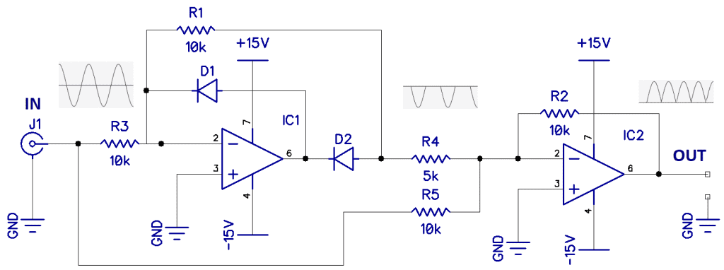
Diode D1 rectifies and inverts the input AC waveform, resulting in the waveform shown above resistor R4. IC2 is an adder and inverter and creates the full-wave rectified output. Note that putting a capacitor across resistor R2 would result in smoother DC at the output.
Peak Detection
Shown below is a peak detector, where the output follows the peak value of the input.
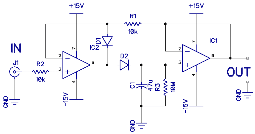
IC1 is doing the detection, and IC2 is just a buffer to preserve a very high impedance needed by capacitor C1, which is charging up to the peak value. Resistor R3 is slowly discharging it. C1 should be a tantalum capacitor.
Peak detector circuits are often used in an audio amplifier or audio mixer to set the input level below the point where clipping might occur.
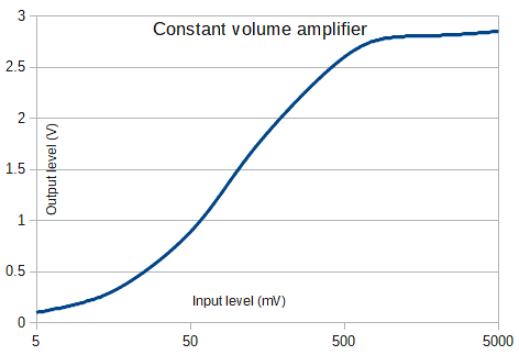
Constant Volume Amplifier (VCA)
The constant volume amplifier shown below is a favorite of mine.
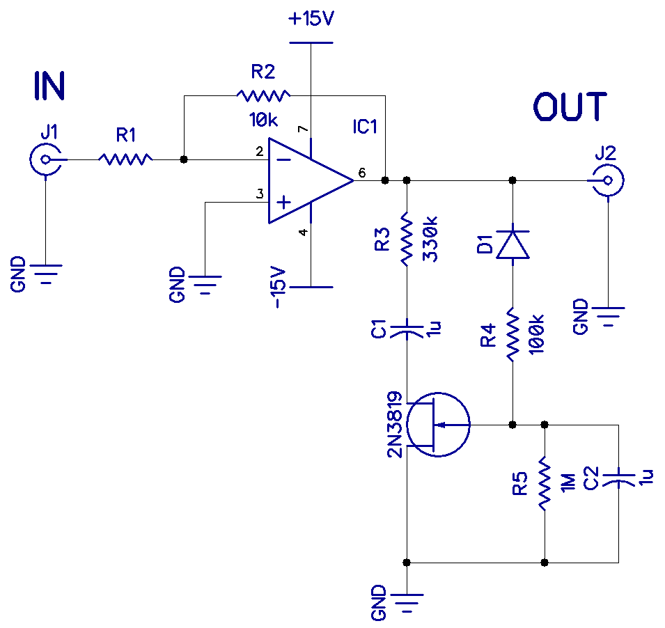
The output level of this amplifier remains constant over a large range of an input signal (about 30dB), with minimal distortion. Below is a chart of the measured response (note that the scale is logarithmic):
Resistor R1 is chosen to set the gain depending on the expected range of input signals. For example:
- 10k Ohms for 50uV-50mV
- 100k Ohms for 500uV-500mV
- 1M Ohms for 5mv-5V
Some other non-linear op-amp applications might include voltage-controlled amplifiers, limiters, and clippers, and log amplifiers.
This concludes this three-part series on operational amplifiers. Be sure to check out the previous articles in the series:
Hope you enjoyed this series on op-amps and hope you build some of these circuits as well. Feel free to leave a comment below if you have any questions!