An RC circuit is a circuit with both a resistor (R) and a capacitor (C). They are a common element in electronic devices and play an important role in the transmission of electrical signals. RC circuits are used as audio filters, electronic timers, oscillators, and more in a wide range of electronics project.

How RC Circuits Work
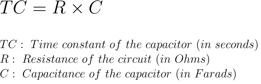
A capacitor can store energy, and a resistor placed in series with it will control the rate at which it charges or discharges. This produces a characteristic time dependence and a crucial parameter that describes a capacitor’s rate of charge and discharge:
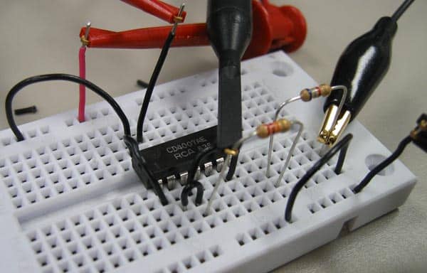
Take a look at the circuit below:
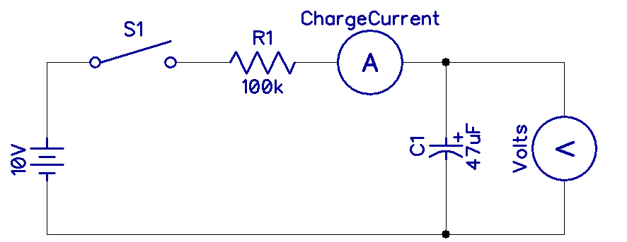
When the switch is closed, current will flow into the capacitor. As the voltage on the capacitor rises, the difference in voltage between the capacitor and the battery decreases, so the capacitor charging current tapers off. As the voltage across the capacitor reaches the voltage of the battery, the capacitor charging slows down.
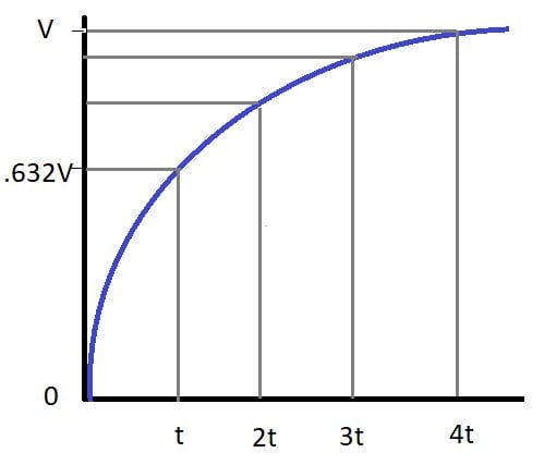
Capacitor Charging
The rate of charge and discharge of a capacitor in an RC circuit is described by the time constant (TC). The time constant is defined as the time it takes the voltage across the capacitor to reach 63.2% of the supply voltage (Vmax):
Capacitor Discharging
If the capacitor in the circuit above were shorted to ground with a jumper wire, the voltage across the capacitor would decrease following a curve like this:
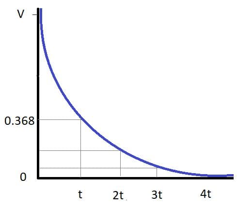
In this case, the time constant is reached when the voltage has dropped to 36.8% of Vmax.
How to calculate the charge time of an RC circuit
As an example we will calculate the time it will take a 1,000 uF capacitor to charge to 63.2% of Vmax with a 100K Ohm resistor:
Time constant = 0.001 F x 100,000 Ohms = 100 seconds
The capacitor will take 100 seconds to charge.
Hope this article has helped you get to know RC circuits better! Feel free to leave a comment below if you have questions about anything.