
In the article What Is Current?, we discussed two main types of current – direct, and alternating current, with a focus on direct current. For this article, we will be focusing on alternating current.

Alternating Current
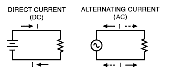
Electric current is defined as the flow of charge. Unlike direct current, which is the flow of charge in one direction, alternating current is an electric current that reverses direction periodically.
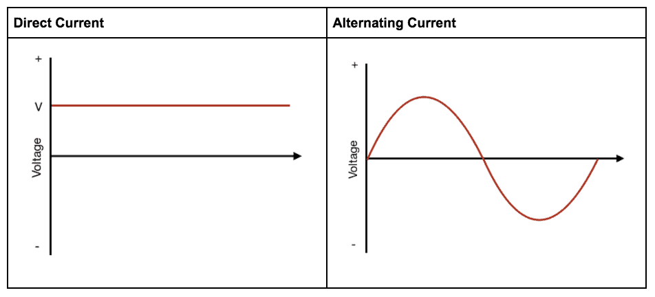
Here is a graphical representation of Direct Current vs Alternating Current:
Alternating current is the backbone of our electricity transmission systems. Back in the late 1880s, Nikola Tesla and Thomas Edison fought over whether we should use AC or DC transmission systems to supply electricity. And this was known as the ‘War of the Currents’ with Edison backing direct current and Tesla supporting alternating current.
Unfortunately, direct current had a significant problem, and it wasn’t easy to convert it to higher or lower voltages. High voltage was required for transmission to reduced power loss. On the other hand, alternating current can easily reach high voltages through the use of transformers.
Today, alternating current is commonly used in our homes. However, direct current is undoubtedly making a comeback as it powers computers, electric vehicles, PV cells, etc. The reason for this is the fact that direct current is much easier to store.
The Alternator
An alternator is an electrical generator that produces alternating current. Its early development was through Michael Faraday and Hippolyte Pixii. Generators usually produce alternating current via the rotation of the rotor; however, in the 1830s, there wasn’t much use for AC. Given this, commutators, a rotary electrical switch, was used to convert the output into direct current.
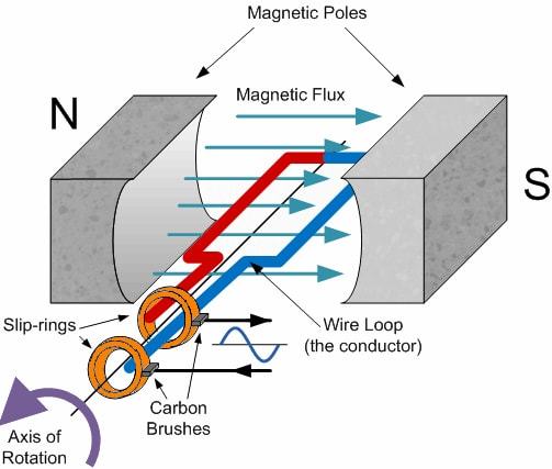
The generator involves rotating a coil in a magnetic field. As one side moves up, the other side moves down through the magnetic field. Current is induced when the coil cuts perpendicular to the magnetic field lines. As a result, the current direction constantly changes as its frequency is dependent on the speed of the rotor.
AC Waveform
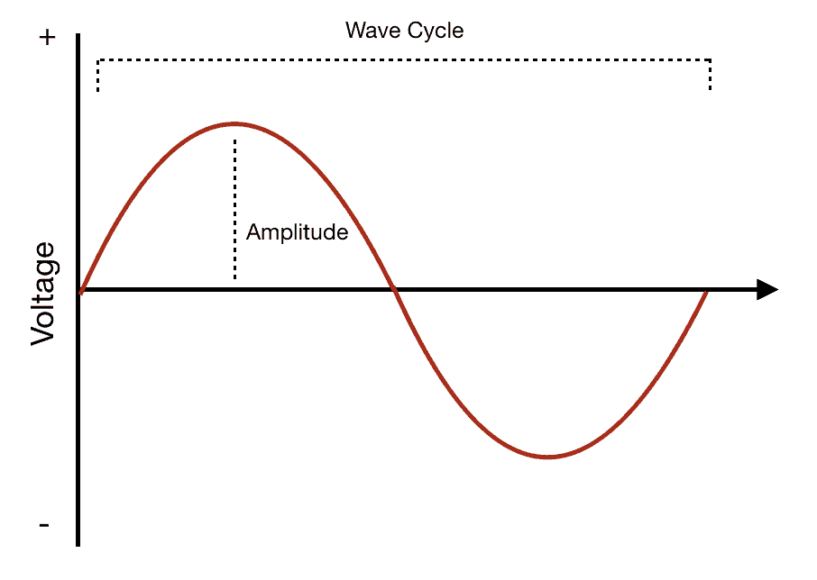
The waveform of AC has an amplitude and a wave cycle. The amplitude corresponds with the peak voltage. The frequency of the wave is the number of wave cycles that occur per second, and the period of the wave is the time it takes to complete one cycle.
Now, how do we accurately measure the voltage of an AC wave given that it is constantly changing?
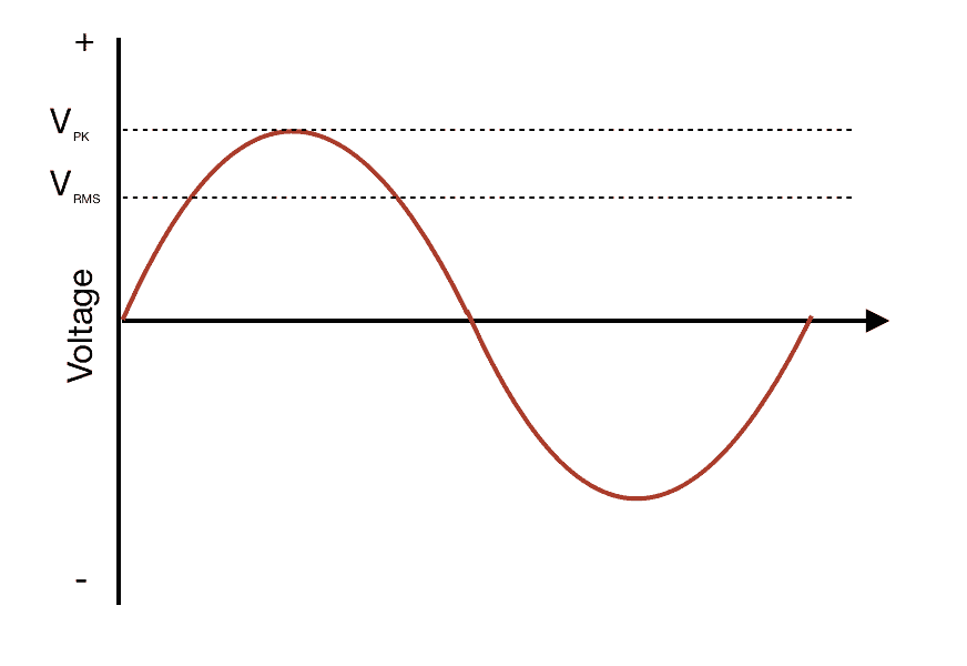
We can accurately measure the AC wave voltage by measuring the root-mean-square value, known as RMS. Take note that most AC values are also RMS values. Power sockets from the grid supply 240 V of electricity, which is the RMS voltage value of the AC supply. And to calculate the RMS value, we can use the following method.
Let’s use the first 180 degrees of the wave cycle as an example. Splitting up the curve by 180/n degrees of spacing between mid-ordinates (n = # of mid-ordinates), we get the following diagram:
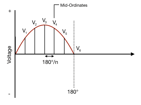
Using this information, we can calculate the RMS voltage value for the curve using the following equation:
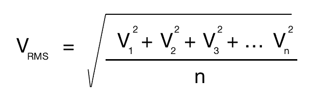
The voltage RMS value is also useful when converting AC to DC. The RMS value is what ends up being the stable DC voltage.
Transformer
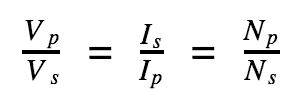
Transformers are used to change the voltage of alternating current in an electric circuit. As mentioned earlier, one of the reasons why AC voltage was chosen to power the electric grid is because it is easily stepped up and down. Meaning the voltage can be altered through the use of a transformer.
Faraday’s law of induction explains how a transformer works. This law states that the induced voltage in a circuit (secondary winding) is proportional to the rate of change over time of the magnetic flux through that circuit, and a varying current in the primary coil produces a different magnetic flux in the transformer’s core. In simple words, the current in the primary winding results in an induced current in the secondary winding. Below is the illustration of the relationship between the voltage, current, and windings of the coils.
Converting AC to DC
The easiest way to convert alternating current to direct current is by using a component known as a rectifier. One of the most common types of rectifiers is a bridge rectifier, a diagram of which can be seen below.
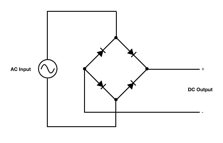
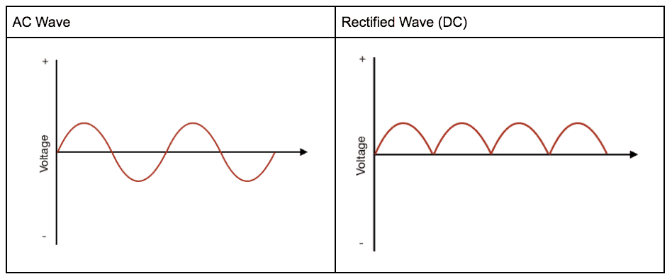
A bridge rectifier consists of 4 diodes in a bridge configuration. A diode is a circuit component that only allows for the flow of current in one direction. Its use is to convert AC to DC because the direct current is current that moves in only one direction. This results in the following wave conversion:
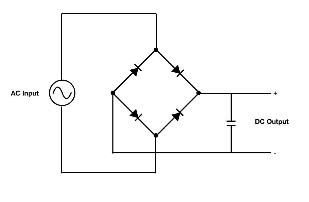
Consider the DC wave above as a pulsating wave. Through this, it can resolve quickly by adding a smoothing capacitor to the circuit, as shown below. The smoothing capacitor provides a more stable and constant source of voltage by charging at peaks and discharging during voltage drops.
Graph of smoothed wave:
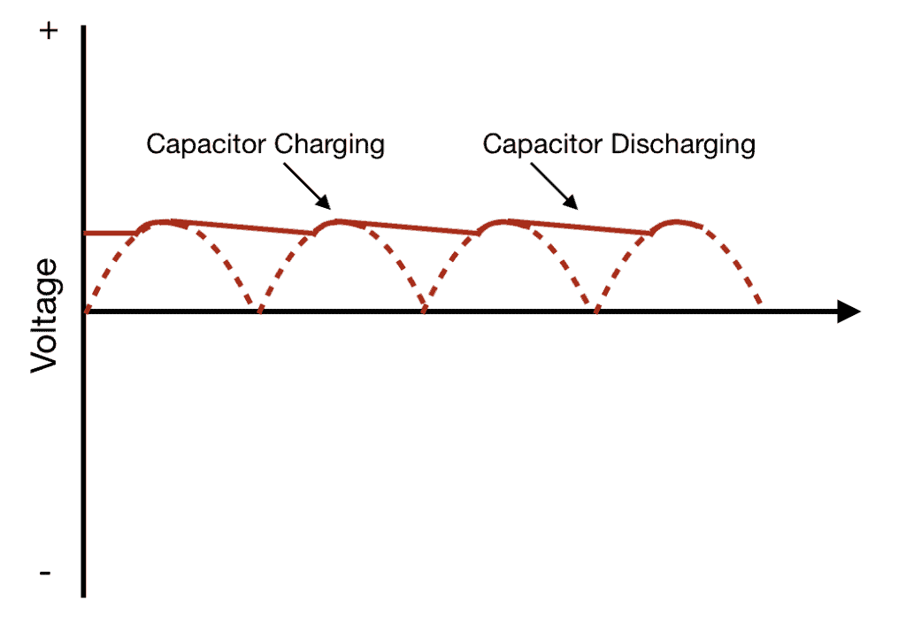
A smoother wave provides for a more stable source of DC voltage, which enables the circuit to power a multitude of devices and components. Alternating current continues to be crucial to our everyday life even if we don’t notice it as much. Thanks for reading and feel free to leave a comment below if you have any questions.

In the US the typical outlet supplies 120VAC, not 240VAC.
Please add this to the above article.🙂
Thank You,
Ralph Rastaetter