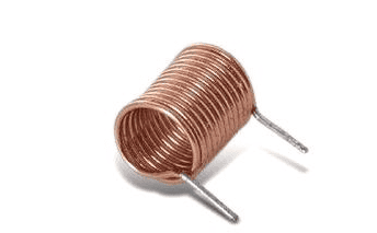
An inductor is a passive two-terminal electrical component that consists of a coil of wire. It is constructed like a resistor that has a simple length of wire coiled up. It stores energy in a magnetic field when electric current flows through it. An inductor typically consists of an insulated wire wound into a coil around a core designed to take advantage of magnetism and electricity. An inductor changes every time the current flows through it.

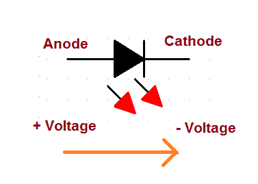
The time-varying magnetic field induces an electromotive force in the conductor described by Faraday’s law of induction. However, Lenz’s law states that the induced voltage has a polarity that opposes the change in current that created it. Therefore, inductors oppose any changes in current through them.
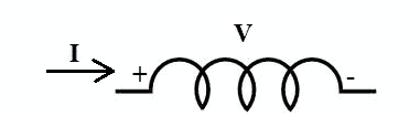
An inductor is capable of storing energy in the form of magnetic fields. As the electricity flows into the coil from left to right, it generates a magnetic field in a clockwise direction.
Common Uses of Inductors
Uses of inductors depend in electrical transmission requirements. It can be used in the following:
- In chokes
When AC flows through inductors, it creates a current flow in the opposite direction. Then, the inductor chokes the AC flow and passes the DC. This is used in a power source where the AC supply converts into DC.
- In tuning circuits
Through the use of inductors, the tuning circuits can select the desired frequency. Electronic devices such as radio tuning circuits and television use capacitors along with the inductor. It modifies the frequency and helps to select within multiple channels of frequency.
- To store energy in a device
Inductors can store energy. The energy is stored as a magnetic field and will disappear when the power supply is removed. You can see this in computer circuits where power supplies can be switched.
- As sensors
Inductive proximity sensors are very reliable in operation and are contactless. The main principle behind it is inductance, which is the magnetic field in the coil opposing the flow of electric current. The proximity sensors mechanism is used in traffic lights to detect traffic density.
- As relays
A relay behaves as an electrical switch. The use of an inductor coil in the switch that comes in contact with the flow of AC produces a magnetic field.
- In induction motors
In induction motors, inductors control the speed of the motor. The shaft in the motor will rotate due to the magnetic field produced by the alternating current. You can fix the speed of the motor according to the frequency of the power supply from the source.
- As transformers
You can design a transformer using a combination of inductors with a shared magnetic field. Power transmission systems illustrate one of the major uses of transformers. They are used to decrease or increase power transmission as step-down or step-up transformers.
- As filters
You can use a combination of inductors and capacitors as filters. The input signal frequency while entering the circuit is limited with the use of these filters. As the frequency of supply increases, the inductor’s impedance also increases.
Faraday’s Law of Induction
As discussed in the previous article on electromagnetism, Michael Faraday experimented on a current flowing through a coil of wire to produce a magnetic field. He watched to see if the magnetic field will induce a current in the second coil of wire but unfortunately, it did not generate a magnetic field. Later on, he realized that a changing magnetic field causes an electric current in a loop of wire. This idea is what we now call Faraday’s Law of Induction.
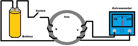
Faraday’s Experiment
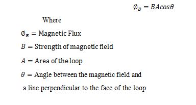
Faraday’s Law of Induction states that a changing magnetic field will induce an electromotive force (emf) in a loop wire. Electromotive force causes electrons to move and form a current. Changing the area of the loop of wire and changing the angle between the loop and the magnetic field induces a current. This is because of a property that most directly induces emf known as magnetic flux. Magnetic flux is the total magnetic field that runs through a loop of wire, and when this field changes, it induces an electromotive force.
The Magnetic Flux equation is given by:
Different Types of Inductors
There are different types of inductors depending on their material type.
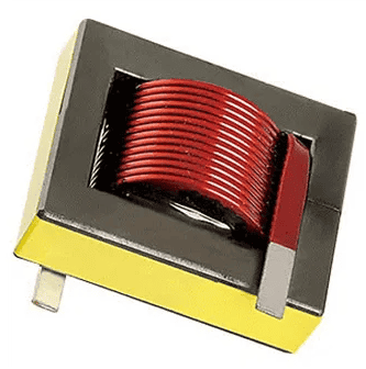
Air Core Inductor
Air core inductors are also known as ceramic core inductors since ceramic is the most commonly used material for inductor cores. Its main goal is to give a form for the coil. It has very low core losses and high-quality factor, making it ideal for high-frequency applications where low inductance values are required. Also, ceramic has a very low thermal coefficient of expansion. Even for a range of operating temperatures, the stability of the inductor’s inductance is high. There will be no increase in the permeability value due to the core material since ceramic has no magnetic properties. Constructing RF tuning coils, filter circuits, and snubber circuits use air-core inductors to ensure a lower peak inductance and in high-frequency applications such as TV and radio receivers. They are also used in the Theil network of some audio amplifiers.
Sample Features:
- Tolerance: ± 2%
- Inductance: 0.85 mH
- Wire gauge: 18 AWG
- DC resistance: 0.44 Ohms
- Power handling: 30 Watts RMS
Iron Core Inductor
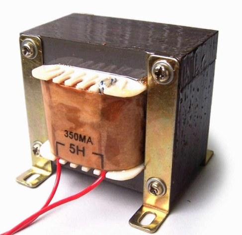
Iron core inductors are the best option when you need small inductors. They have high power and high inductance value. However, they’re limited in high-frequency capacity. It is applicable in audio equipment, but unlike other core inductors, it has limited applications.
Ferrite Core Inductor
It is also called as ferromagnetic material. It has magnetic properties and consists of mixed metal oxide of iron and other elements to create the crystalline structures.
There are two types of ferrites – soft ferrites and hard ferrites. They are classified according to the magnetic coercivity, which is the magnetic field intensity required to demagnetize the ferromagnetic material from a complete saturation state to zero. A ferrite is composed of XFe204, where X represents transition materials. The magnetized material combinations mostly used are manganese and zinc (MnZn), or zinc and nickel (NiZn). There are a lot of applications of the ferrite core. It can be used at high and medium frequencies, in switching circuit and Pi Filters.
Sample Features:
- Proprietary 5H and 10H ferrite materials and equivalent
- Suitable for ≥ 150 kHz range
- Operating temperature ranges from −25°C to +120°C
- UL 94 V–0 flame retardant rated to base and bobbin
Calculating the Voltage Across an Inductor
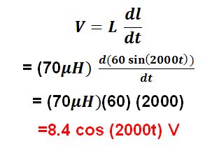
In calculating the voltage across an inductor, we use the formula:
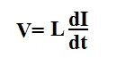
For us to calculate the voltage across the inductor we need to find L first. L is the inductance expressed in Henry and the current’s derivative going through the inductor.
Example: If the current going through the inductor is 60sin (2000t) and its inductance is 70μH, what is the voltage across the inductor?
Calculating the Current Through an Inductor
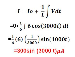
In calculating the voltage across an inductor, we use the formula:
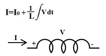
For us to calculate the current through the inductor we need to find L first. L is the inductance expressed in Henry and the voltage’s integral going across the inductor.
Note: Io is the initial current going through the inductor, if there is any.
Example: If the voltage across an inductor is 6cos (3000t) V and the inductance of the inductor is 6μH, what is the current going through the inductor? (Initial Conditions: Io = 0A)
Calculating the Inductance of a Coil of Wire
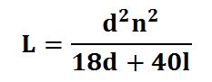
In calculating the inductance of a coil of wire, we use the formula:
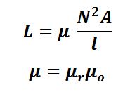
The magnetic flux around the coil causes its inductance. The stronger the magnetic flux for a specific value of current, the larger its inductance. It means that you’ll have a higher inductance with more turns of the coil and lower inductance with fewer turns. Therefore, the formula above shows that the inductance is proportional to the number of turns squared.
How to Build Wire Coil Inductors
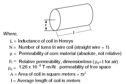
To calculate the specific inductance in Henries, we can use the formula:
Where:
- L = inductance in Micro Henries [µH]
- d = diameter of the coil from one wire center to another wire center. It should be specified in inches.
- l = is the length of the coil specified in inches
- n = the number of turns
But in doing so, remember the following:
- The length of the coil used in the inductor should be equal to or 0.4 times the diameter of the coil.
- As shown in the formula above, the inductance of the air-core inductor varies as the square of the number of turns. Thus, the value of length is multiplied four times if the number of turns is doubled. The value of length is multiplied by two if the number of turns is increased up to 40%.
- Use an enamel coated magnet wire to make the coil.
How to Wind the Coil
- First, the coil must be wound on a plastic former of appropriate diameter and should be equal to the required core diameter.
- The winding must be tight and adjacent turns must be as close as possible.
- After the winding is complete, slowly withdraw the core without disturbing the coil.
- Apply a thin layer of epoxy over the coil surface for mechanical support.
- Lastly, remove the insulation from the coil ends.
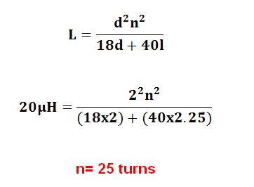
Example: Let’s say you need to make an inductor which produces an inductance of 20 μH. The diameter of the coil is 2 inches and the coil length is 2.25 inches. You need to find the number of turns of the coil.
Substituting the values in the above formula where:
- L = 20 inches
- d = 2 inches
- l = 2.25 inches
Wire Coil Characteristics that Affect Inductance
1. Number of wire wraps or turns in the coil
The more turns of wire in the coil, the greater the amount of magnetic field generated measured in Amp-turns. This means that the more turns of wire in the coil results in greater inductance, and fewer turns of wire results in less inductance.
2. Coil area
The coil area is measured lengthwise through the coil, at the cross-section of the core. A larger coil area gives less opposition to the formation of a magnetic field flux given an amount of field force. It means that larger coil area results in greater inductance and a smaller coil area results in less inductance.
3. Coil length
The longer the coil’s length, the lesser the inductance, and conversely, the shorter the coil’s length, the greater the inductance. A widely spaced coil makes a relatively long coil. This coil type has fewer flux linkages due to the greater distance between each turn. Therefore, it has relatively low inductance. On the other hand, the coil that has closely spaced turns makes a relatively short coil. This close spacing increases the flux linkage, increasing the inductance of the coil. Doubling the length of a coil while keeping the same number of turns cuts the value of inductance in half.
4. Core material
The greater the magnetic permeability of the core, the greater the inductance. The magnetic core of a soft-iron core is a better path for magnetic lines of force than the nonmagnetic core. The soft-iron magnetic core’s high permeability has less reluctance to the magnetic flux, resulting in more magnetic lines of force. This increase in the magnetic lines of force increases the lines of force, cutting each coil loop. It then increases the inductance of the coil.
Thanks for reading and feel free to leave a comment below if you have any questions.