Digital Logic or Boolean Logic represents signals and sequences in a digital circuit through numbers. It is a system of rules that allow us to make complicated decisions based on simple yes/no questions. It becomes the foundation of digital computing and explains how circuits and hardware communicate within a computer. Digital logic is the basis of computing and many other electronic devices as well as control systems found in this continually advancing digital world. It constructs the implementation of computer operations by manipulating the binary values through printed circuit board technology that uses circuits and logic gates. Most electronic devices, including calculators, computers, video games, and watches, contain this feature. Knowledge in digital logic can be an advantage for many people who work with computers and technology like engineers and technicians.

Logic Gates
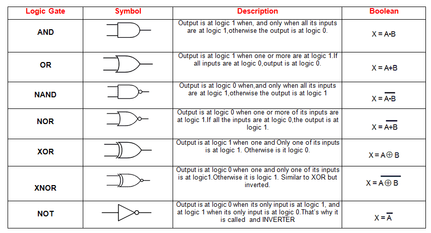
Logic gates are used in a computer to transform the 1s and 0s from input wires. It accepts inputs, and then outputs are results based on their state. The logic gate is a small transistor circuit that is part of different forms in an integrated circuit. Each type of gate has one or usually two inputs and one output.
Digital electronics depends on the actions of just seven types of logic gates shown in the table below.
Truth Table
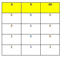
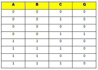
A truth table is used in mathematical representation to represent all the combinations of values for inputs and their corresponding outputs. It is used in logic problems such as Boolean algebra and electronic circuits. The truth table shows all the possible outcomes in a given scenario that are factual. It also shows the results of a logical expression using individual columns for each variable and its corresponding output. The columns for the values of inputs are listed to the left, while the output is in the right.
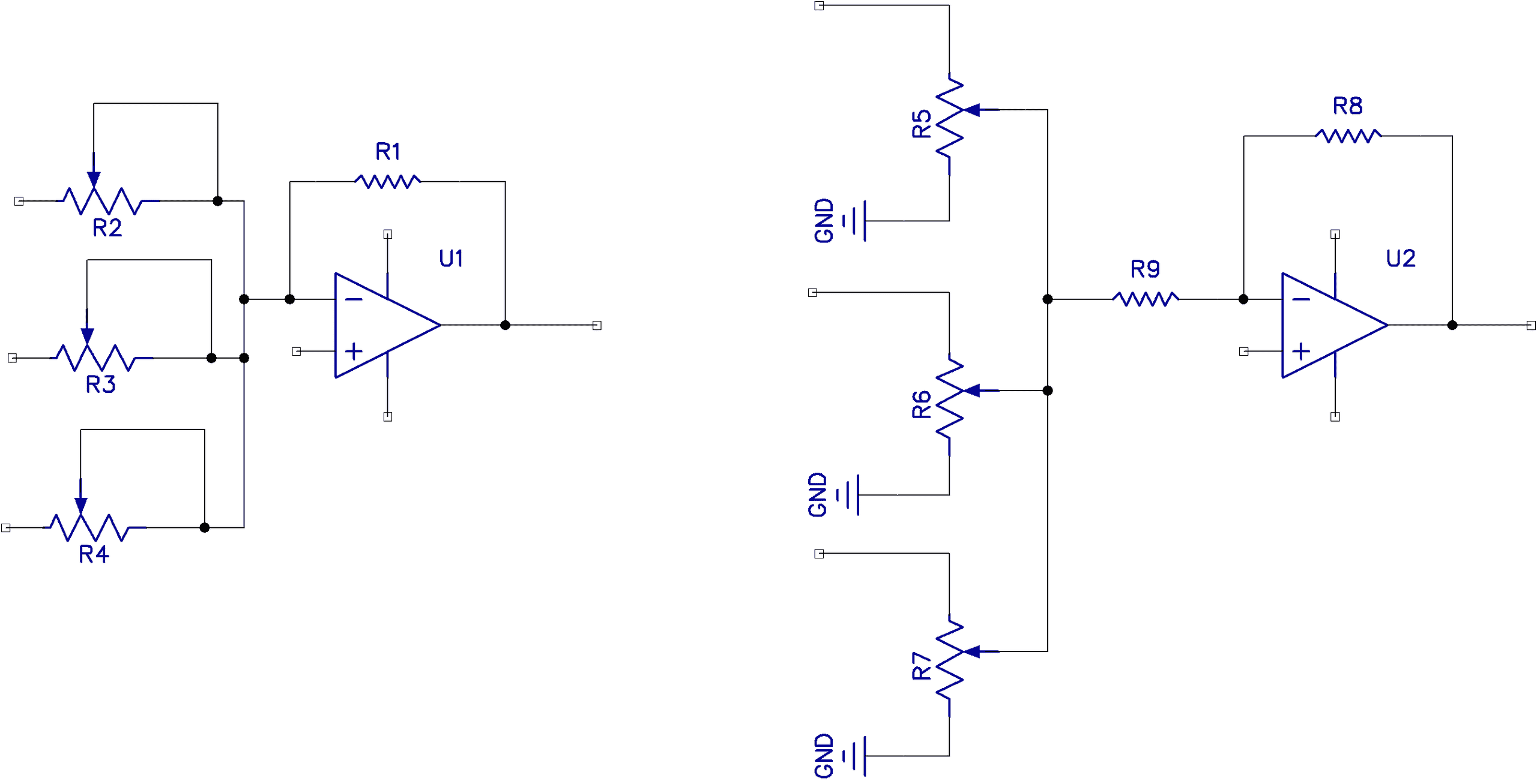
Logic Gates Built with Transistors
Logic gates are built using transistors. The base-emitter diode needs to turn on to drive saturation while the collector voltage concerning the emitter may be near zero.
AND Gate
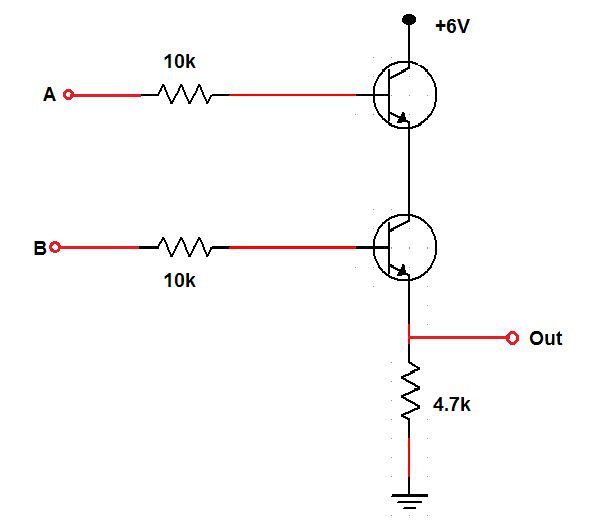
The transistors need to be in series, and both transistors must be in the conducting state for it to drive the output high.
OR Gate
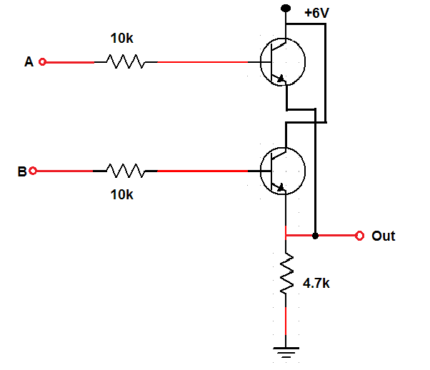
The transistors need to be in parallel because if either of the transistors is conducting, the output will be high.
NAND Gate
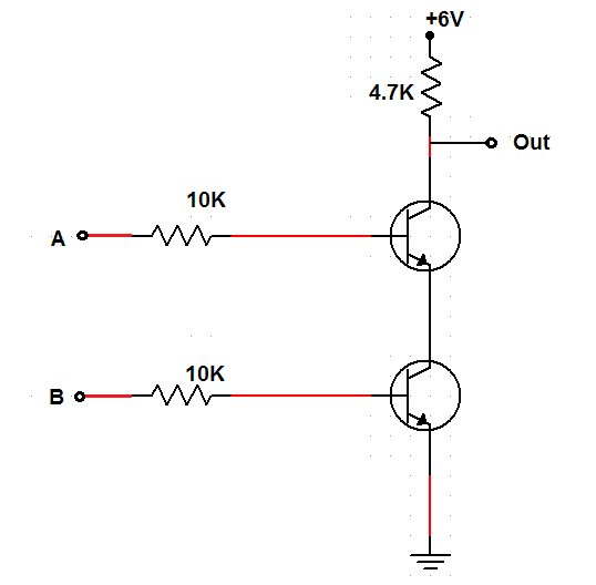
The transistors need to be in series even if the output is above them. The output must be taken down close to the ground potential since it is always high unless both A and B inputs are high.
NOR Gate
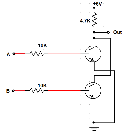
Double Transistor
The transistors need to be in parallel with the output above them so that the output is driven low when either or both inputs are high.
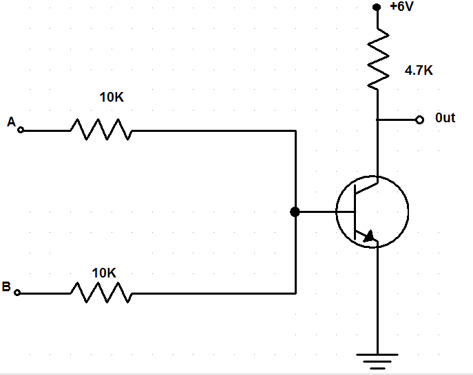
Single Transistor
If either or both of the inputs are high, the output would be low; that’s why only one transistor is used with the two inputs attached to its base through resistors.
Combinational Logic
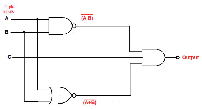
Combinational logic is a digital logic that implements Boolean circuits where the output is a function of the present input alone. The logical function of the current input state, logic “0” or logic “1”, at any given instant time determines the outputs of combinational logic.
Ways to Specify the Function of a Combinational Logic Circuit
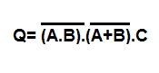
Boolean Expression
It is the algebraic expression that shows the operation of the logic circuit for each input variable.
Logic Diagram
It shows the wiring and connections of each logic gate, which are represented by a specific graphical symbol.
Truth Table
It defines the function of a logic gate using a list that shows all the output states in tabular form for each possible combination of the input variable.
What is a Karnaugh Map?
Karnaugh map is used to simplify Boolean logic expressions. It tells you what output your circuit will have given your inputs. Karnaugh map combines illustrations with common factors and therefore eliminates unwanted variables.
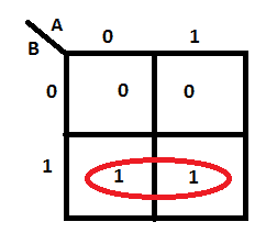
Karnaugh map has rules that we need to follow for the simplification of expressions by grouping cells that contain logic “1”.
The group is not allowed to have a logic “0”. Hence, this is wrong:
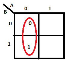
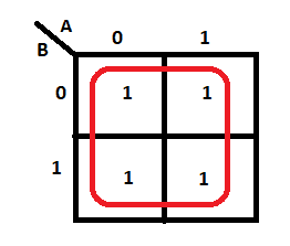
Instead, it should be:
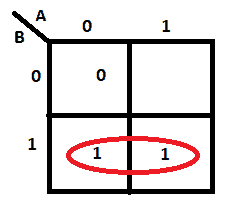
Groups can’t be diagonal but can be either horizontal or vertical. Hence, this is wrong:
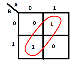
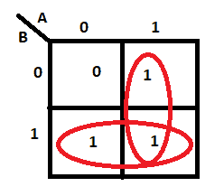
Instead, it should be:
Groups must contain 1, 2, 4, 8, or in general 2n cells. That is if n = 1, a group will contain two 1’s since 21 = 2. If n = 2, a group will contain four 1’s since 22 = 4. Hence, these are wrong:
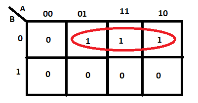
Instead, they can be:
Make sure each group should be as large as possible. Hence, this is wrong:

Note: It didn’t break any Boolean law, but it’s not sufficiently minimal. So it should be:

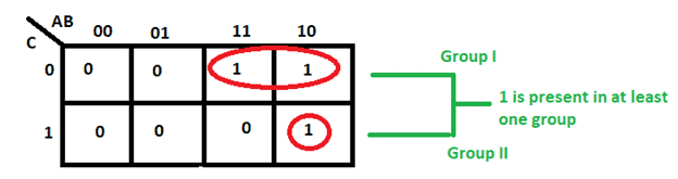
Make sure each cell containing a 1 must be in at least one group.
Groups are allowed to overlap.
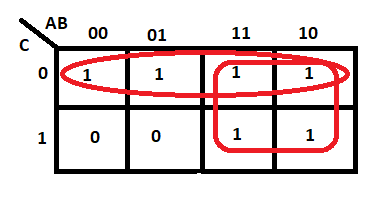
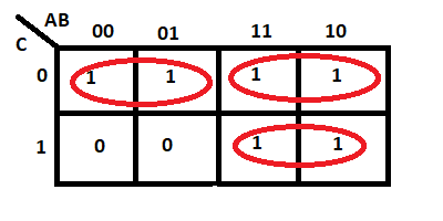
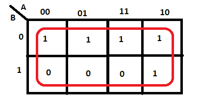
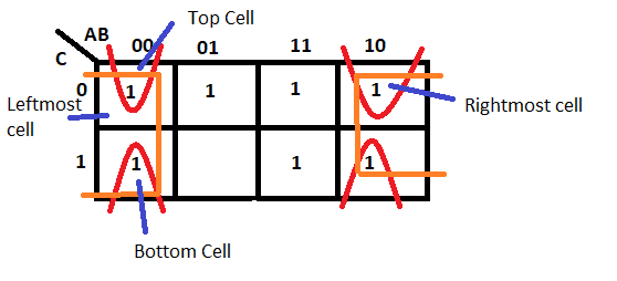
Groups may wrap around the table. The top cell in a column may be grouped with the bottom cell, and the leftmost cell in a row may be grouped with the rightmost cell.
Make sure there are few groups as possible without compromising any of the previous rules. Therefore, this is wrong:

Instead, it should be :

To make everything clear, here is the summary of the rules for Karnaugh Map:
- No zeros allowed in a group.
- No diagonals are allowed.
- Only power of 2 number of cells in each group.
- Groups should be as large as it can be.
- Every logic “1” must be in at least one group.
- Overlapping is allowed.
- Wrap around is allowed.
- Fewest number of groups as much as possible.
Be sure to leave a comment below if you have a question about anything!

The future of computer science is bright. The world needs experts to master binary codes smartly in order to prevent cyber security errors and fraud.