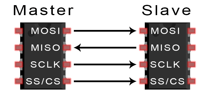
So far, we’ve talked about the basics of SPI communication and UART communication, so now let’s go into the final protocol of this series, the Inter-Integrated Circuit, or I2C.

You’ll probably find yourself using I2C if you ever build projects that use OLED displays, barometric pressure sensors, or gyroscope/accelerometer modules.
Introduction to I2C Communication
I2C combines the best features of SPI and UARTs. With I2C, you can connect multiple slaves to a single master (like SPI) and you can have multiple masters controlling single, or multiple slaves. This is really useful when you want to have more than one microcontroller logging data to a single memory card or displaying text to a single LCD.
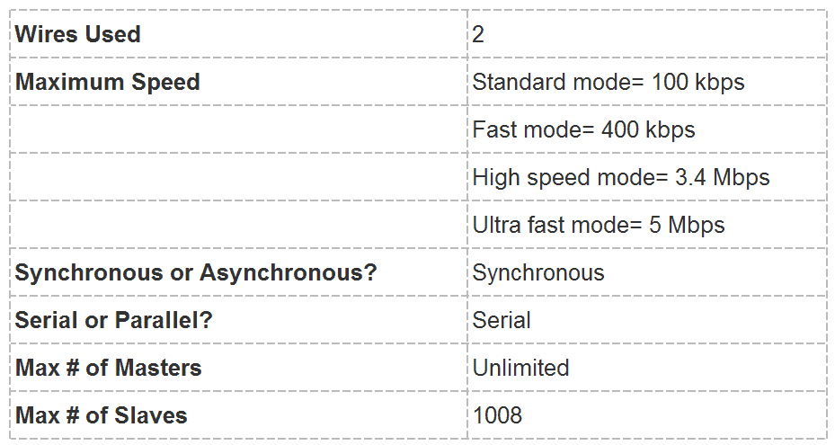
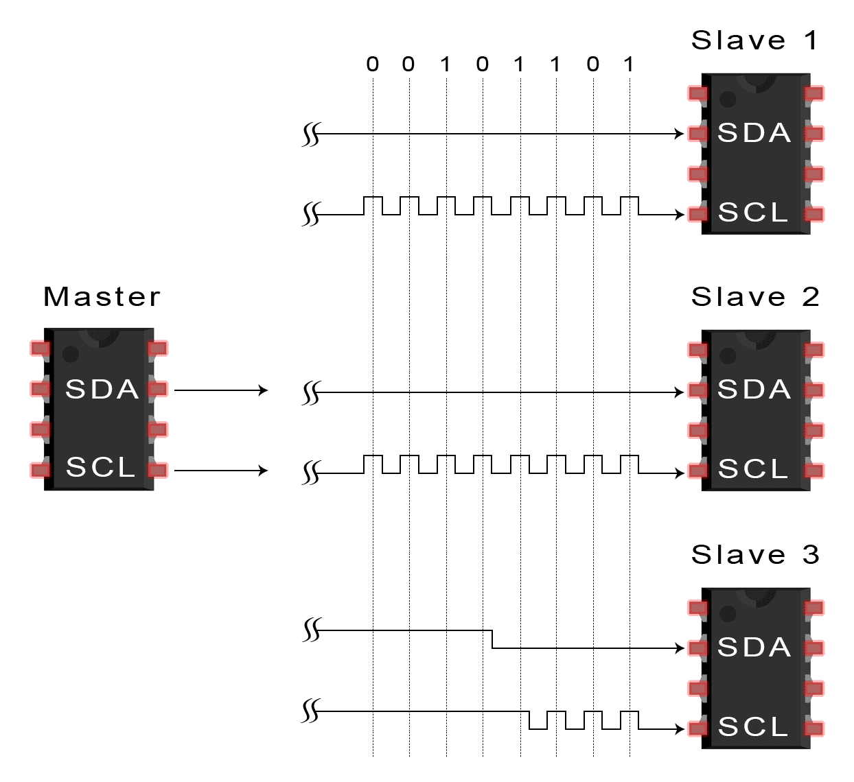
Like UART communication, I2C only uses two wires to transmit data between devices:
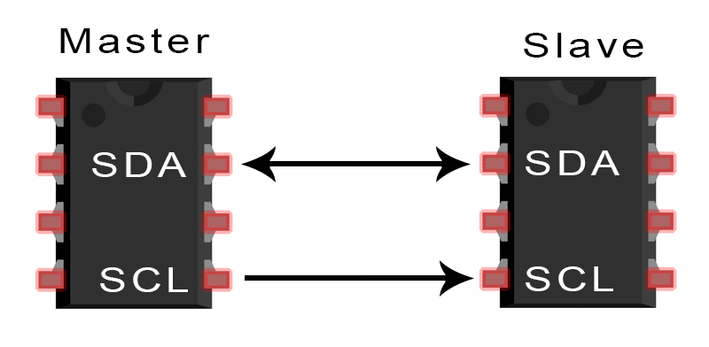
SDA (Serial Data) – The line for the master and slave to send and receive data.
SCL (Serial Clock) – The line that carries the clock signal.
I2C is a serial communication protocol, so data is transferred bit by bit along a single wire (the SDA line).
Like SPI, I2C is synchronous, so the output of bits is synchronized to the sampling of bits by a clock signal shared between the master and the slave. The clock signal is always controlled by the master.
How I2C Works
With I2C, data is transferred in messages. Messages are broken up into frames of data. Each message has an address frame that contains the binary address of the slave, and one or more data frames that contain the data being transmitted. The message also includes start and stop conditions, read/write bits, and ACK/NACK bits between each data frame:
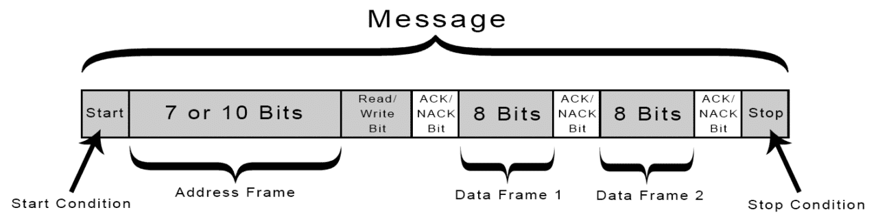
Start Condition: The SDA line switches from a high voltage level to a low voltage level before the SCL line switches from high to low.
Stop Condition: The SDA line switches from a low voltage level to a high voltage level after the SCL line switches from low to high.
Address Frame: A 7 or 10 bit sequence unique to each slave that identifies the slave when the master wants to talk to it.
Read/Write Bit: A single bit specifying whether the master is sending data to the slave (low voltage level) or requesting data from it (high voltage level).
ACK/NACK Bit: Each frame in a message is followed by an acknowledge/no-acknowledge bit. If an address frame or data frame was successfully received, an ACK bit is returned to the sender from the receiving device.
Addressing
I2C doesn’t have slave select lines like SPI, so it needs another way to let the slave know that data is being sent to it, and not another slave. It does this by addressing. The address frame is always the first frame after the start bit in a new message.
The master sends the address of the slave it wants to communicate with to every slave connected to it. Each slave then compares the address sent from the master to its own address. If the address matches, it sends a low voltage ACK bit back to the master. If the address doesn’t match, the slave does nothing and the SDA line remains high.
Read/Write Bit
The address frame includes a single bit at the end that informs the slave whether the master wants to write data to it or receive data from it. If the master wants to send data to the slave, the read/write bit is a low voltage level. If the master is requesting data from the slave, the bit is a high voltage level.
The Data Frame
After the master detects the ACK bit from the slave, the first data frame is ready to be sent.
The data frame is always 8 bits long, and sent with the most significant bit first. Each data frame is immediately followed by an ACK/NACK bit to verify that the frame has been received successfully. The ACK bit must be received by either the master or the slave (depending on who is sending the data) before the next data frame can be sent.
After all of the data frames have been sent, the master can send a stop condition to the slave to halt the transmission. The stop condition is a voltage transition from low to high on the SDA line after a low to high transition on the SCL line, with the SCL line remaining high.
Steps of I2C Data Transmission
1. The master sends the start condition to every connected slave by switching the SDA line from a high voltage level to a low voltage level before switching the SCL line from high to low:
2. The master sends each slave the 7 or 10 bit address of the slave it wants to communicate with, along with the read/write bit:
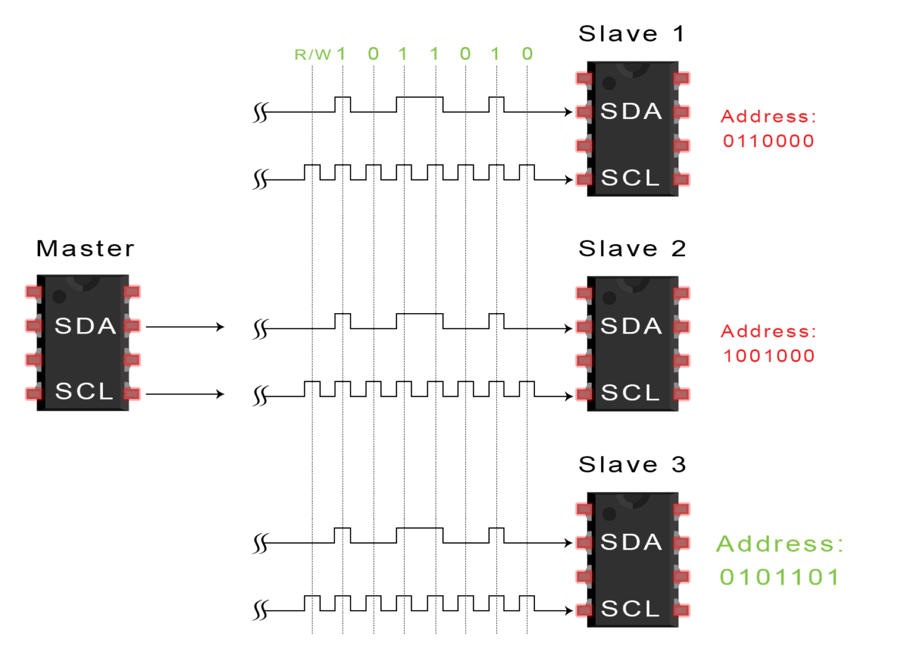
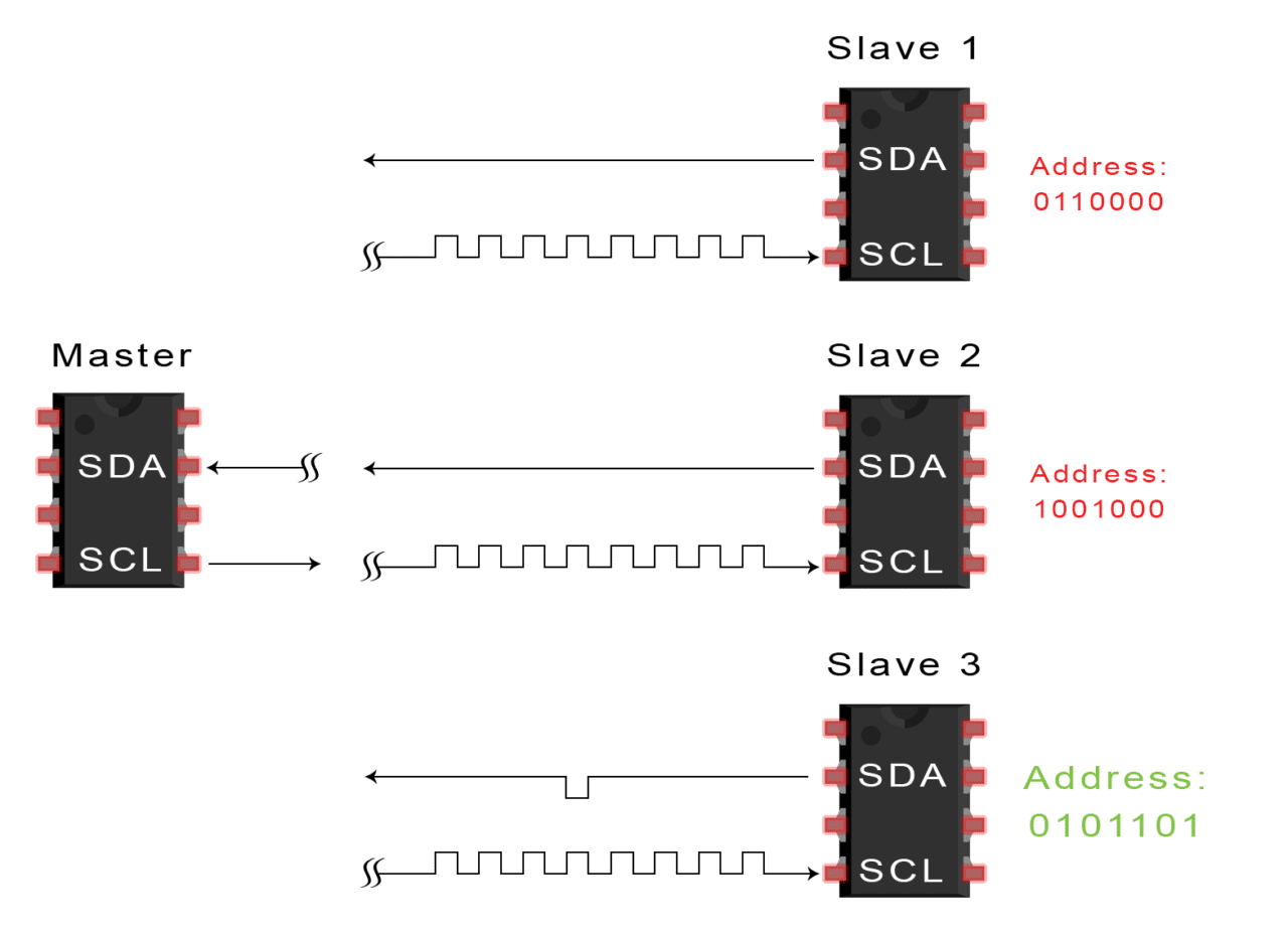
3. Each slave compares the address sent from the master to its own address. If the address matches, the slave returns an ACK bit by pulling the SDA line low for one bit. If the address from the master does not match the slave’s own address, the slave leaves the SDA line high.
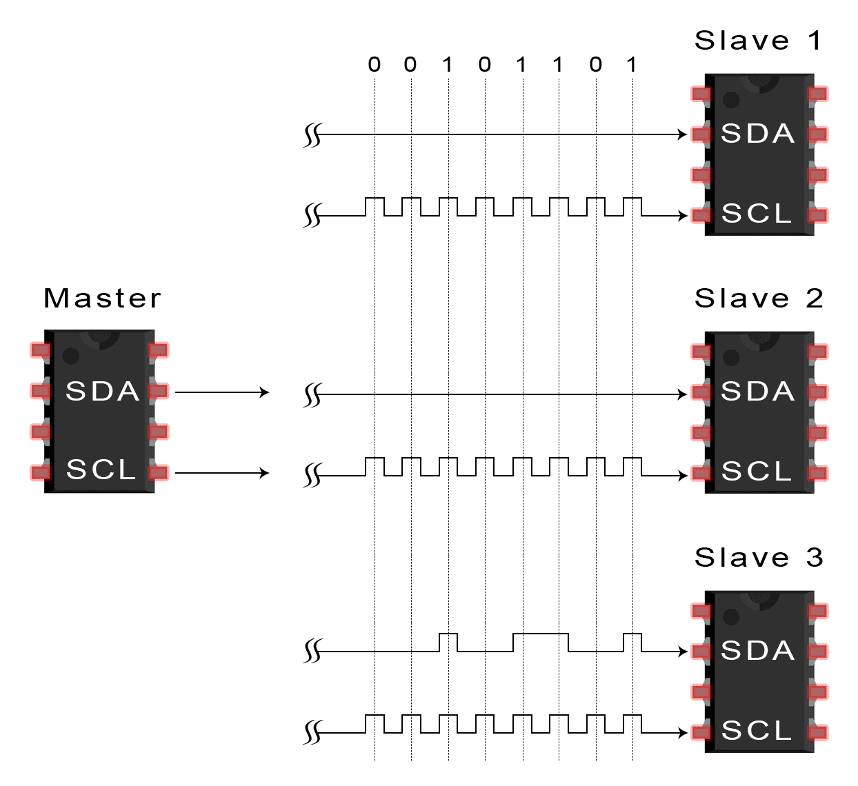
4. The master sends or receives the data frame:
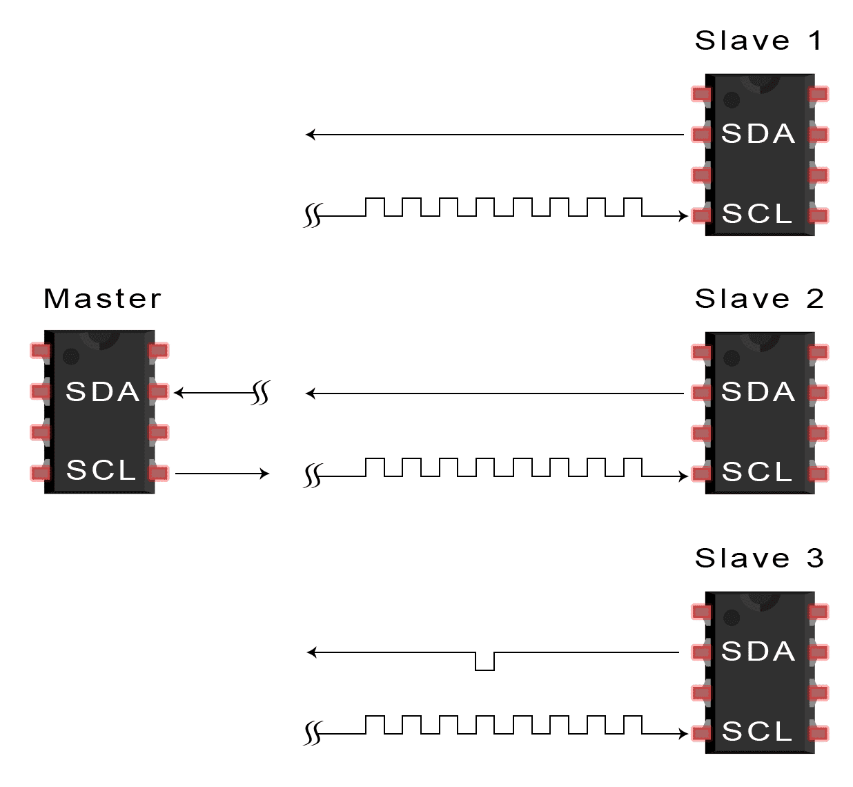
5. After each data frame has been transferred, the receiving device returns another ACK bit to the sender to acknowledge successful receipt of the frame:
6. To stop the data transmission, the master sends a stop condition to the slave by switching SCL high before switching SDA high:
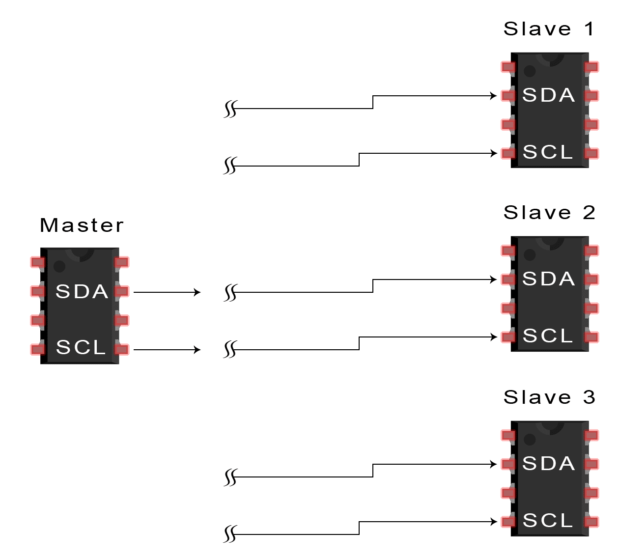
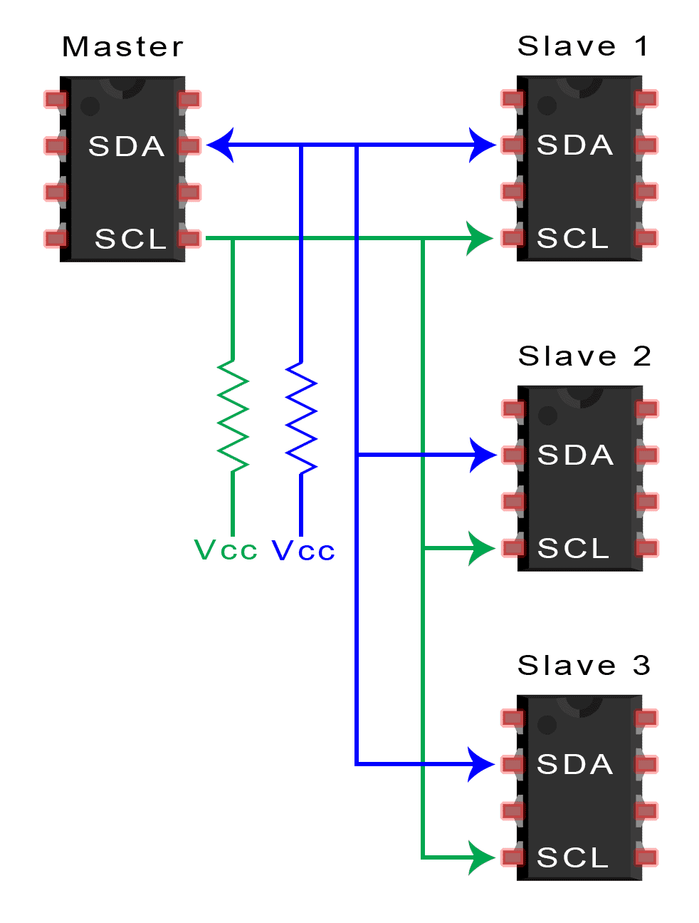
Single Master with Multiple Slaves
Because I2C uses addressing, multiple slaves can be controlled from a single master. With a 7 bit address, 128 (27) unique address are available. Using 10 bit addresses is uncommon, but provides 1,024 (210) unique addresses. To connect multiple slaves to a single master, wire them like this, with 4.7K Ohm pull-up resistors connecting the SDA and SCL lines to Vcc:
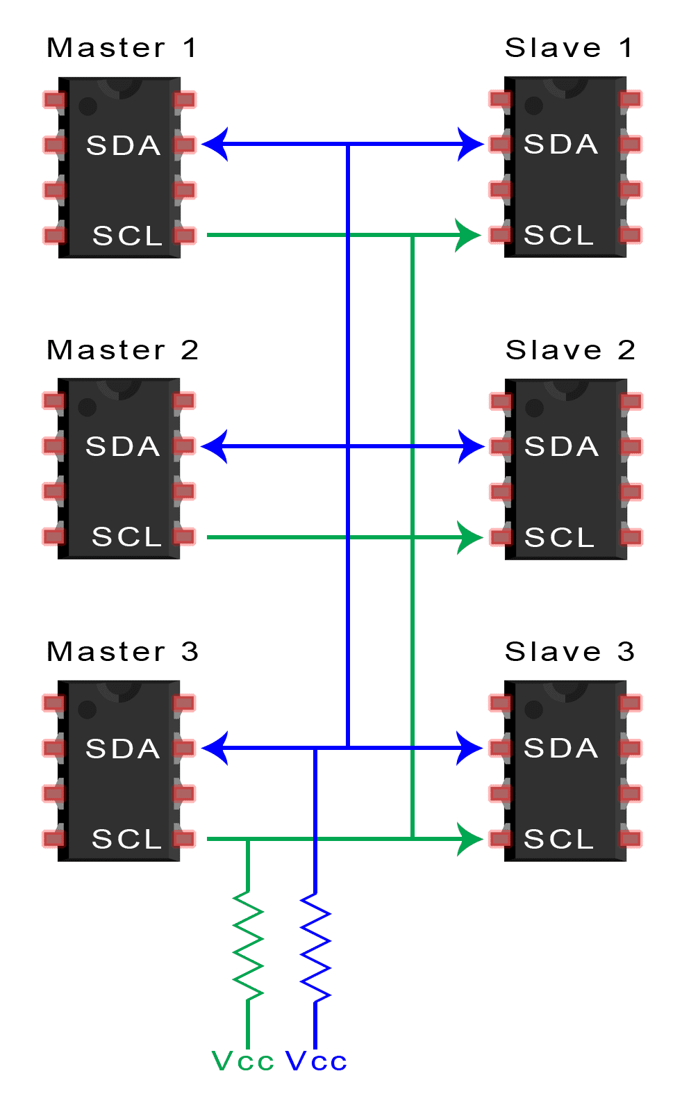
Multiple Masters with Multiple Slaves
Multiple masters can be connected to a single slave or multiple slaves. The problem with multiple masters in the same system comes when two masters try to send or receive data at the same time over the SDA line. To solve this problem, each master needs to detect if the SDA line is low or high before transmitting a message. If the SDA line is low, this means that another master has control of the bus, and the master should wait to send the message. If the SDA line is high, then it’s safe to transmit the message. To connect multiple masters to multiple slaves, use the following diagram, with 4.7K Ohm pull-up resistors connecting the SDA and SCL lines to Vcc:
Advantages and Disadvantages of I2C
There is a lot to I2C that might make it sound complicated compared to other protocols, but there are some good reasons why you may or may not want to use I2C to connect to a particular device:
Advantages
- Only uses two wires
- Supports multiple masters and multiple slaves
- ACK/NACK bit gives confirmation that each frame is transferred successfully
- Hardware is less complicated than with UARTs
- Well known and widely used protocol
Disadvantages
- Slower data transfer rate than SPI
- The size of the data frame is limited to 8 bits
- More complicated hardware needed to implement than SPI
Thanks for reading! Hope you learned something from this series of articles on electronic communication protocols. In case you haven’t read them already, part one covers the SPI communication protocol, and part two covers UART driven communication.
If you have any questions or have anything to add, feel free to leave a comment below. And be sure to subscribe to get more articles like this in your inbox!


Great series of posts. Thanks for sharing this!
Thanks for this,u are a genius,i need simple circuit for invater and power Bank circuit
Many thanks. Working with this – while knowing how it actually works makes it so much better. Thank you for taking the time to explain it so well
Thanks very nice information. I liked all your articles and the way you explained all.
Please add for PCIe communication as well.
Simple and easy to understand. I suggest some example to put in practice
GOOD JOB!
@TheArduinoGuy not bad, although the multi-master arbitration part is very, see; https://t.co/2msABa9WxH
Thanks, but can’t find any about correct I2C initialization (as describe in NXP document)
Great post. Thank you very much !!
SIR THIS IS VERY USEFUL FOR BEGINERS PLEASE ALSO SEND THE CAN PROTOCOL ALSO PLEASE
PLEASE
PLEASE ….infinite TIMES….
Please share CAN article also
Here’s a intro tutorial on CAN: https://www.circuitcrush.com/can-networking-tutorial/
Step 1 confuses me. You say “1. The master sends the start condition to every connected slave by leaving SCL high and switching SDA to low:” and yet the diagram shows the SDA line going from low to high. Am I seeing this correctly?
Step 6 is similarly confusing as you say “6. To stop the data transmission, the master sends a stop condition to the slave by switching SCL high before switching SDA high:” The diagram shows both lines high already with SDA going low before SCL. I follow your written explanation but I don’t think your diagrams do.
You’re right, step 1 could have been written better. I re-wrote it and hopefully cleared it up a bit… In step 6, I think it’s the direction the bits are being sent that might be a little confusing. In the diagrams, picture the bits travelling from left to right, so in step 6, the SCL line switches high before the SDA line switches high.
Otherwise good articles and helpful explanations. Thanks for the work.
Where is information about clock stretching? Very useful feature
awsome article
Good article on I2C.
Really helpful
DtcInstall
Thanks. This is a very interesting article. I’m not fully understanding point 4 however. When master is transmitting to its chosen slave would the sda line of all slaves not be pulled high as they are all sharing the same line?
Have the same question. It’s like all the other slaves will also receive the data which is not meant for them. If it is correct, is it possible to transmit data to only one specific slave with I2C?
I also have this same question. It seems like it’s possible for devices that are not selected to also read the SDA pin because they’re on the same line. Is this protocol on the assumption that all slaves and masters are part of one system and so none are trying to steal data?
Hi
thanks for great content.
Does the sck pulse continuously in this protocol ?
No, it only pulses during the exchange between Master and Slave.
The SDA line, like the SCLK line, is indeed common to all devices and so will always be the same. The key thing is that only the slave device with the matching address actions a write command and drives the SDA line for a read command.
I’m sure the OP drew the diagrams this way to show the actual data transfer between the addressed device and the master for clarity.
good article .i think it is better to explain about arbitration clock stretching /synchronization about why pull ups ….
@framboise314 excellent !
Did I miss it or do you talk about how to handle communication with multiple I2C modules that use same Address ?
You could add a chapter about I2C multiplexing and how to handle it for example with a TCA9548A .
woow superb ….. its a really basic concepts of i2c…..
thanks for this website….
go head yaaar.
superb ,nice ,great ……………
This article is very good for beginner to study the serial communication protocols. The concepts are easily understood.
Hi Nice article. But waveform of Start and End conditions need to be switched :)
Great article! One thing though:
Under “Single Master With Multiple Slaves”, while describing how using a 7-bit or a 10-bit address frame, it’s written so: 128 (27) and 1024 (210), while it should be 128 (2^7) and 1024 (2^(10)). I was stuck there for a while ._.
When you state the SCL goes “high” or “low”, does this basically mean it is “ON” or “OFF”? It’s just a clock signal at a specific frequency based on a crystal? No data is sent over this line; it’s just the set clock frequency? And what is a typical frequency?
Since polarity and phase cannot be set as with SPI, would this not be a disadvantage? Are these parameters sometimes adjusted for better communication, and thus SPI might be a better choice over I2C ?
HI: I have spent several day trying to get the I2C network to work with no luck. I am trying to connect a RTC 3231 and a 16X2 lcd display.Each will work seperatly but when I connect both of them, the RTC works but the display doesn’t.
Appreciate any help you can offer.
George Whitaker gmwhjt@frontier.com
Explanation is very good. But in I2C, 7-BIT addressing, 10-BIT Addressing Explanation is not there.
NICE
Great work. Can you please post such articles on CAN?
Grateful information…
Nice article. But waveform of Start and End conditions need to be switched :)
Simple and great article. thanks
Can you add I3C as well. i3C is very new . But just want to glimpse of it.
Very useful information.Very clear and perfect.
Thank u for posting this topic
Very Useful Stuff.
I need the know how to trigger the sensors using I2C commands also need clarification to set the delay using I2C in my project.
Please share your response.
Thank you !!!
what about usb protocol?
Sir, my humble thanks for a tremendous article. Great piece of Technical knowledge dissemination. Request you as well as other knowledgeable members to advise how to know target device address. Does the target device, in my case, a memory ic, an eeprom of 25 series, have a fixed address, or is given one? Pls help me out. Thanks
Very nicely explained. Kudos to the author!
nice article on i2c communication
In the Start & STOP cases, the SDA line is represented wrongly
Start: SDA goes high to low (In the diagram, it is low to high)
Stop: SDA goes from low to high(In the diagram, it is high to low)
Notice the direction of transmission. In the diagram,the right is ahead of the left.
Nice Article about I2C communication, I have used it in my college time.
Its very helpful for my metro project.
Thanks
Aakash patel
Nice article & got the clear understanding of the I2C protocol. thank you a lot….
In step 1) – Both SCL and SDA are going from low to high. But explanation says the opposite. Am I not reading the signals correctly. Could you please explain it.
Read the signal from right to left. In this article, the waveforms are shown in the opposite sense that you would see on an oscilloscope. I had the same issue.
Thanks for this information.
Much appreciated. Very helpful. thank you very much!
thank you – very useful
The content was concise and I could grasp it in one reading, also the diagrams were of great help. Much appreciated.