For some projects, you may need to control high-power devices such as a motor, valve, or any 220AC electrical device. Unfortunately, the Raspberry Pi cannot handle the power requirements of such devices. The only way to go around this barrier is to include a control interface. We call this interface a relay, and it sits between the Raspberry Pi and the high-power device.

In this tutorial, we will learn what a relay is, how relays work, and how to connect a relay to the Raspberry Pi to control high-power devices. We will use Python to program everything. To demonstrate, we will build an example project that uses a thermistor to activate a 5V relay when the temperature exceeds a certain threshold.
What is a Relay?
A relay is an electrically operated switch. The difference between a manual switch and a relay is that a manual switch opens or closes circuits through an operator’s physical actions. On the other hand, a relay opens or closes circuits when actuated by a low power electronic signal.

A relay consists of four main parts: the electromagnet, movable armature, switch point contacts, and a spring. I will discuss how these components work together to control a high-power current in a safe, low-voltage environment.
How a Relay Works
The following diagram shows the pins of a relay.
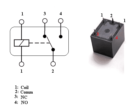
A relay has two main circuits—the primary circuit and the secondary circuit:
- Primary circuit: the controlling circuit. It provides the signal to switch ON or OFF the relay. There is an electromagnetic coil that generates a magnetic field when there is a flow of current. This magnetic field attracts a movable armature that is in the relay core. When we remove power from the coil, the movable armature returns to its original position with the help of a small spring. At the end of the movable armature is a movable contactor.
- Secondary circuit: the controlled circuit. This is where we connect the load, such as pumps or valves. When the movable armature is attracted to the coil, it closes the circuit on the secondary circuit, thereby providing a direct connection between the Comm and the NO pin.
High Voltage Terminals
We refer to the relay type described above as a Single Pole Double Throw (SPDT) relay. This is because the common connection has a contact that moves between the NO and NC contacts. When the relay is OFF, i.e., when there is no power to the coil, the common contact changes position to the NC contact. Similarly, when we apply an electric current to the coil, the common contact moves from the NC contact to connect with the NO contact. In other words:
- Normally Open is a contact that does not allow current to flow in its normal state, in this case, when the coil is NOT energized. They only allow current to flow in the secondary circuit when the coil is energized.
- Normally Closed is a contact that allows current to flow in its normal state, in this case, when the coil is NOT energized. They will stop the flow of current in the secondary circuit when the coil is energized.
- Common terminal is the part of a relay that moves. It selects between the NC and NO terminals depending on the state of the coil.
How to Wire High Voltage Devices to the Relay
WARNING: WORKING WITH HIGH VOLTAGES AND HIGH VOLTAGE DEVICES IS DANGEROUS AND CAN CAUSE FIRE, INJURY AND EVEN DEATH. DO NOT BUILD THE CIRCUITS BELOW WITHOUT PROPER TRAINING OR THE ASSISTANCE OF AN EXPERIENCED ELECTRICIAN.
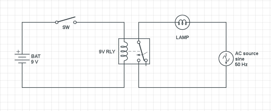
The following circuit diagram shows how to connect a high voltage device in the normally open configuration. In this state, the switch (SW) is open, so no current flows in the primary circuit. Consequently, no current will flow through the relay coil, and the lamp will remain in the OFF state.
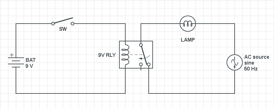
In the diagram below, we demonstrate the normally closed configuration. The common terminal will be at the normally closed contact in its normal state, thereby completing the circuit with the 220VAC source. This means that the lamp will be in the ON state.
How to Connect a 5V Relay to the Raspberry Pi
Now that we have seen how the relay works, it’s time to connect it to our Raspberry Pi. We will need the following components:
- Raspberry Pi
- Breadboard
- Jumper wires
- SRD-5VDC-SL-C 5V relay
- One BC337 transistor
- One 1K Ohm resistor
- One 1N4007 diode
The signal to activate the relay is generated by pin GPIO17:
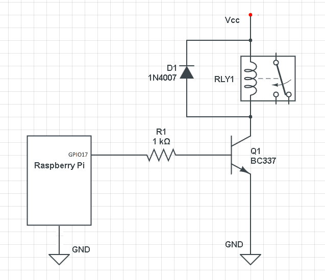
Note that most SRD-5VDC-SL-C 5V relay boards already include R1, D1, and Q1.
In the circuit diagram above, we connect a diode between the relay’s coils (in parallel with relay coil) to prevent voltage spikes or back electromotive force (EMF) when power is disconnected from the relay.
When a current is flowing through the relay coil, a magnetic field is created. So when the current suddenly stops flowing, the magnetic field in the coil needs to dissipate. This causes a huge EMF to build up on the open junctions of the relay coil. A diode will block the flow of back EMF, thereby protecting our circuit.
5V Relay Controlled by a Thermistor
In this section, we will build an example project. We will connect the SRD-05VDC-SL-C relay to a 120V-240V lamp and turn on the relay when the temperature reading from a thermistor drops below a threshold value.
RC Circuits
The Raspberry Pi does not have a built-in analog to digital converter (ADC), so to use analog sensors like a thermistor, we need to use an RC circuit. The step response of an RC circuit can be used to measure resistive devices like potentiometers, flex sensor, and thermistors.
In the diagram below, we see the two charging and discharging curves of a capacitor with a square wave input. When the input voltage suddenly changes from 0 to Vs, the capacitor gradually charges up through the resistor until the voltage across it reaches the battery’s supply voltage:
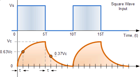
On the other hand, when the input voltage suddenly changes from Vs to 0V, the charge between the capacitor’s plates decays exponentially.
We can use the equation below to express the time constant as a function of the capacitor voltage and the supply voltage as:

In the equation above, Vc, Vs, and C are known. We will write a program that will measure the time t and R. Using these parameters, we will use the Steinhart-Hart equation to convert the resistance to a temperature value.
Connecting the Thermistor to the Raspberry Pi
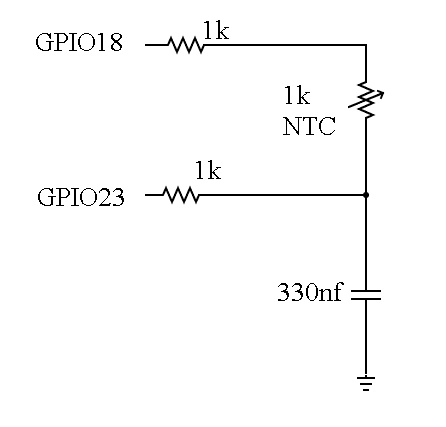
To use the RC step response concept in our temperature sensor project, add the circuit below to a separate section of the breadboard following the wiring diagram below.
These are the parts you will need:
These are the steps we will take to measure the resistance of our thermistor:
- Make GPIO18 an input.
- Make GPIO23 an output and write a value of 0 to discharge the capacitor.
- Initialize the clock and record the time.
- Convert GPIO23 to an input pin and GPIO18 to an output pin and write a value of 1 to GPIO18. This will charge the capacitor.
- When the capacitor voltage reaches roughly 40% of Vs (Raspberry Pi pin voltage) The input pin (GPIO23) will register the input as HIGH. The time it takes for the pin to change from LOW to HIGH is proportional to the resistance of the thermistor at that time.
Programming the NTC Temperature Sensor
We are going to use the PiAnalog Python library (which you can find here) to program the temperature sensor. It is a convenient library which you can use to measure resistive circuits on your Raspberry Pi.
To install the PiAnalog library on your Raspberry Pi, enter these commands into the terminal:
git clone https://github.com/simonmonk/pi_analog.git
cd pi_analog
sudo python3 setup.py install
Now that the library is ready, we will write the Python code. This code will output the temperature (in Celsius) measured by the thermistor to the terminal. Copy the code to a text editor on the Raspberry Pi and save the file as “myFile.py”:
from PiAnalog import *
import time
p = PiAnalog()
while True:
print("%.2f"% p.read_temp_c(3950,1000))
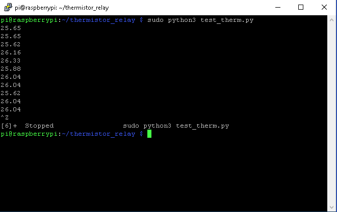
time.sleep(5)This library uses Python3, so run the code above with the command sudo python3 myFile.py.
The line print("%.2f"% p.read_temp_c(3950,1000)) calls the function p.read_temp_c(), and it passes two parameters which are the NTC constant and the NTC resistance at 25oC.
When we run this code, we get the following output:
Programming the 5V Relay
At this stage, we have successfully managed to convert the resistance measurement of the thermistor into a temperature reading. Now we need to add some code to control the relay.
In the program below, we define a temperature threshold of 30oC. When the reading from the thermistor increases above that threshold, the relay is activated and the light bulb turns on.
Copy the code below to a text editor on the Raspberry Pi and save it as a file named “myFile.py”:
from PiAnalog import *
from gpiozero import LED
import time

p = PiAnalog()
relay = LED(17)

while True:
  print("%.2f"% p.read_temp_c(3950,1000))
  time.sleep(5)
  if (p.read_temp_c(3950,1000) > 30):
    relay.on
    print("relay ON")

  else :
    relay.off()
    print("relay OFF")
Run the code above with the command sudo python3 myFile.py.
In the previous steps, we already connected the signal pin of the 5V relay to pin GPIO17 on the Raspberry Pi. Here, we use the LED library because it is an easy way to control the digital pins of the Raspberry Pi.
We use the line if (p.read_temp_c(3950,1000) > 30) to set a threshold of 30oC. If the temperature exceeds that threshold, the relay.on function will turn GPIO17 high, which activates the relay and turns on the light bulb.
Thanks for reading! Be sure to leave a comment below if you have questions about anything!


Good helpful tutorial, thank you for sharing