If you have ever used a tone control on a radio, stereo, or guitar, you have used an audio filter. An audio filter is a circuit that has been designed to let certain audio frequencies pass in a signal but block other frequencies out.

One example of an audio filter is the cross-over module in a loudspeaker box. It sends low frequency sounds to the woofer and blocks them from the tweeter. Other uses might include blocking low-frequency rumble from a turntable, eliminating hiss from a tape deck, or eliminating mains hum.
Types of Audio Filters
There are three main groups of filters:
- Passive filters – use passive components only, such as resistors, capacitors, and inductors, and are suitable to handle high voltage and power levels. Produce very little distortion or electrical noise.
- Digital filters – the signal gets digitized by an analog to digital converter, processed by a microcontroller, then sent to a digital to analog converter.
- Active filters – uses active components such as transistors and op-amps. We will look at this group in detail.
The most useful filters with ease of use and best all-around performance are the Sallen Key active filters. Sallen Key filters are two-pole filters, meaning they have two reactive components (capacitors). All of the circuits below are based on this design.
Low Pass Filter
In a low pass filter, frequencies above a certain point are blocked:
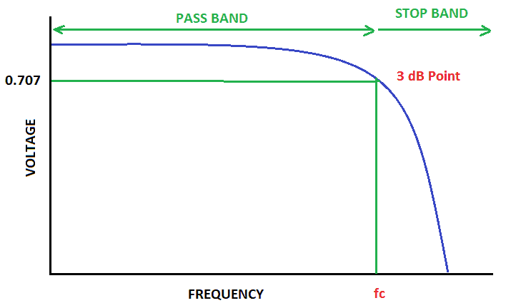
In figure 1 above, you see that frequencies from zero to fc pass without attenuation. But at fc, the signal starts to roll off, and it becomes 3dB down or 0.707 of the original value.
For example, say we want to attenuate an amplifier’s response after the audible range (about 20kHz) to prevent oscillations. We can do this by connecting a low pass filter to the output of the amplifier.
Here is the schematic for a 20kHz low pass filter:
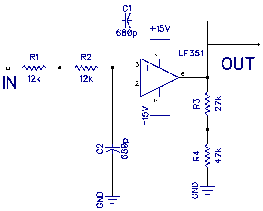
The gain is set by resistors R3 and R4. With R3 at 27k and R4 at 47k, the gain (A) is:
A = (R3 + R4) / R4
A = (27k + 47k) / 47k
A = 1.6
So the gain is 1.6.
The cutoff frequency (Fc) is calculated using this formula:
Fc = 1 / (2 * Pi * R1 * C1)
With R1 at 10k Ohms and capacitor C1 at 680 pF, the cutoff frequency becomes:
Fc = 1 / (2 * Pi * 10k * 680 pF)
Fc = 23kHz
So all frequencies above 23kHz will be attenuated. This is not perfect, but it’s close enough. If you replace R1 and R2 with potentiometers, the cut off can be adjusted a bit. Note that the units in the formula above should be converted to Ohms and Farads before performing the calculation.
High Pass Filter
In a high pass filter, frequencies below a certain point are blocked:
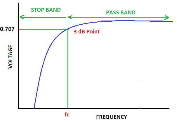
In figure 3 above, you see that frequencies above fc pass without attenuation. But at fc and below, the signal starts to roll off and becomes 3dB down or 0.707 of the original value and continues to roll off as we go down in frequency.
As another example, we can attenuate an amplifier’s response to frequencies below the audible range (about 20Hz) by connecting a high pass filter to the output of an amplifier.
This is the schematic for a 20Hz high pass filter:
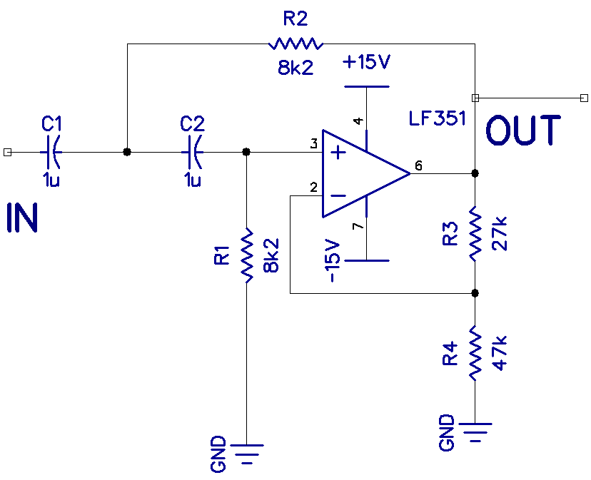
The gain is set with resistors R3 and R4 as in the previous circuit.
With this filter, C1 is 1 uF and R1 is 8.2K Ohms, so the cutoff frequency is:
Fc = 1 / (2 * Pi * 8.2k * 1 uF)
Fc = 19.4Hz
Remember to convert the resistance and capacitance values to Ohms and Farads before performing the calculation.
So all frequencies below 19.4Hz will be attenuated.
Band Pass Filter
In a band pass filter, frequencies above and below two points are blocked:
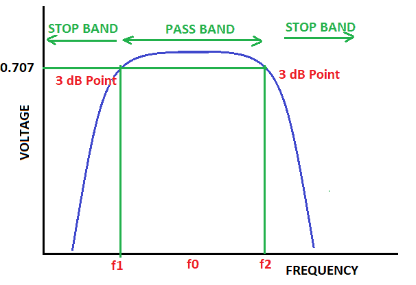
In figure 5 above, you see that frequencies between f1 and f2 pass without attenuation.
One use for a band pass filter could be to tighten the audio range from a microphone before it is fed into a recording device.
This is the schematic for a 1kHz band pass filter:
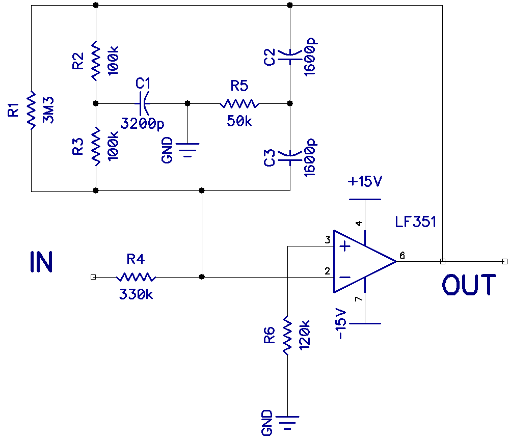
This is a classic twin t filter. In the feedback path from pin 6 to pin 2, there is a low-frequency filter (R2, R3, and C1) and a high-frequency filter (C2, C3, and R5). The two filters act together to pass only a narrow band of frequencies. The gain of this narrow band is at a maximum at the center frequency.
The center frequency (Fo) is calculated with this equation:
Fo = 1 / (2 * Pi * R * C)
For example, with R at 100k Ohms and C at 1600 pF, the center frequency becomes:
Fo = 1 / (2 * Pi * 100k * 1600 pF)
Fo = 1kHz
For the band pass filter to work properly, the capacitor in the low frequency filter (C1) needs to be twice the value of the capacitors in the high frequency filter (C2 and C3). Also, the resistors in the low frequency filter (R2 and R3) need to be twice the value of the resistor in the high frequency filter (R5).
Notch Filter
In a notch filter, frequencies between two points are blocked:
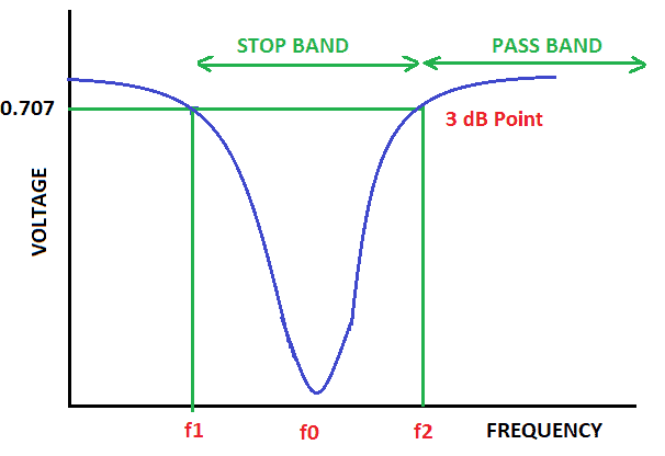
In figure 7, you see that frequencies below f1 and above f2 pass without attenuation.
Notch filters can be used to get rid of certain frequencies in an audio signal. For example, they can be used to remove the 60Hz mains hum from the output of an audio amplifier.
Here is the schematic to build a 60Hz notch filter:
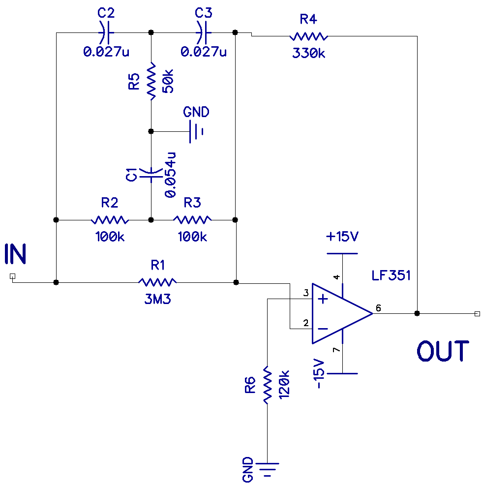
This also is a classic twin t filter. There is a low frequency filter (R2, R3, and C1) and a high frequency filter (C2, C3, and R5). The two filters act together to exclude only a narrow band of frequencies. In a notch filter, the gain is at a minimum at the center frequency.
For example, with R at 100k Ohms and C at 0.027 uF, the center frequency becomes:
Fo = 1 / (2 * Pi * 100k * 0.027 uF)
Fo = 59Hz
For the notch filter to work properly, the capacitor in the low frequency filter (C1) should be twice the value of the capacitors in the high frequency filter (C2 and C3). Also the resistors in the low frequency filter (R2 and R3) should be twice the value of the resistor in the high frequency filter (R5).
That concludes this article on active audio filters. Hope you build one (or all) of these filters for yourself, they are really fun to play around with! Let us know in the comments below if you have questions about anything.

In regard to the bandpass filter example, what frequencies would the low frequency filter and high frequency filter filter out, if the center frequency is 1kHz?
Hey Graham, you’ve swapped the power pins on that LF351, the chips will be destroyed. Newbies will be frustrated.
I am going to build a band pass filter to my midrange speaker in my 3-way system. 1. In general, the question I have is the HPF 1st then attached to the LPF and then the polarity is reversed to the midrange? 2. The wiring of the HPF is the capacitor is parallel then the inductor in series (cap 1st inductor 2nd) and the LPF inductor 1st and in parallel and capacitor 2nd in series? Thanks