In this tutorial, we’re going to build a web server that will control the Arduino’s GPIO pins from anywhere in the world. Whenever you start working with a new platform, it’s always good to get the basics down before moving on to more complex projects. LEDs are a great way to test new platforms since they’re easy to setup and troubleshoot, so we will build a project that turns on and off LEDs as a way to demonstrate how to control the Arduino’s GPIO pins from a web browser.

Arduino Ethernet Shield
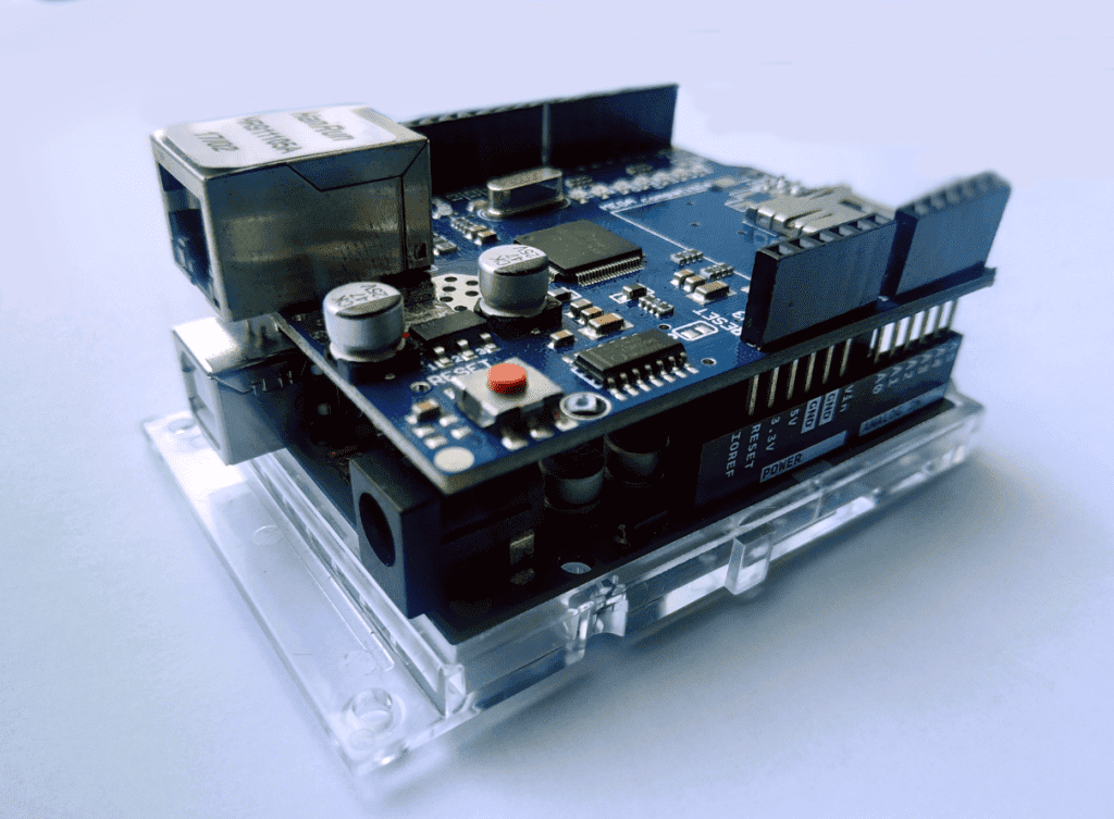
The Arduino Ethernet shield is a PCB that allows the Arduino to connect to the internet. It is based on the Wiznet W5xxx line of Ethernet chips. These chips have a network stack capable of both TCP and UDP. However, the shield only allows wired connection via the RJ45 connector, so if you’re looking for a wireless internet solution, you might want to look at an ESP8266 board instead. The Arduino Ethernet shield has an integrated microSD card reader, which you can use to store files for your webpage.
You can still interface with most of the Arduino’s pins using the female header pins of the Ethernet shield. Simply line up the pins of the shield and Arduino and press them down until they’re in a comfortable fit. The pins you cannot use are pins 10 (SS), 11 (MOSI), 12 (MISO), and 13 (SCK). These are SPI pins, which the Arduino uses to communicate with the Ethernet shield.
Preparing the Hardware
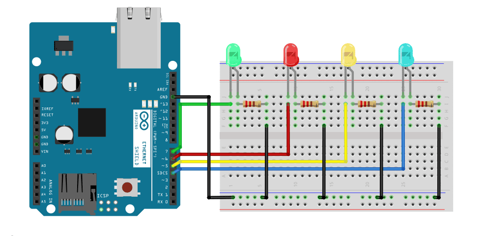
For this project, we are going to control 4 LEDs using a webpage hosted by an Arduino with an Ethernet Shield. In order to do that, we need the following items:
- Arduino UNO
- Arduino Ethernet shield
- LEDs (4)
- 200-1K Ohm current limiting resistors (4)
- Jumper wires
- Breadboard
Connect all of the components according to the wiring diagram below:
To learn more about the Arduino, check out our Ultimate Guide to the Arduino video course. We teach Arduino programming and circuit building techniques that will prepare you to build any project.
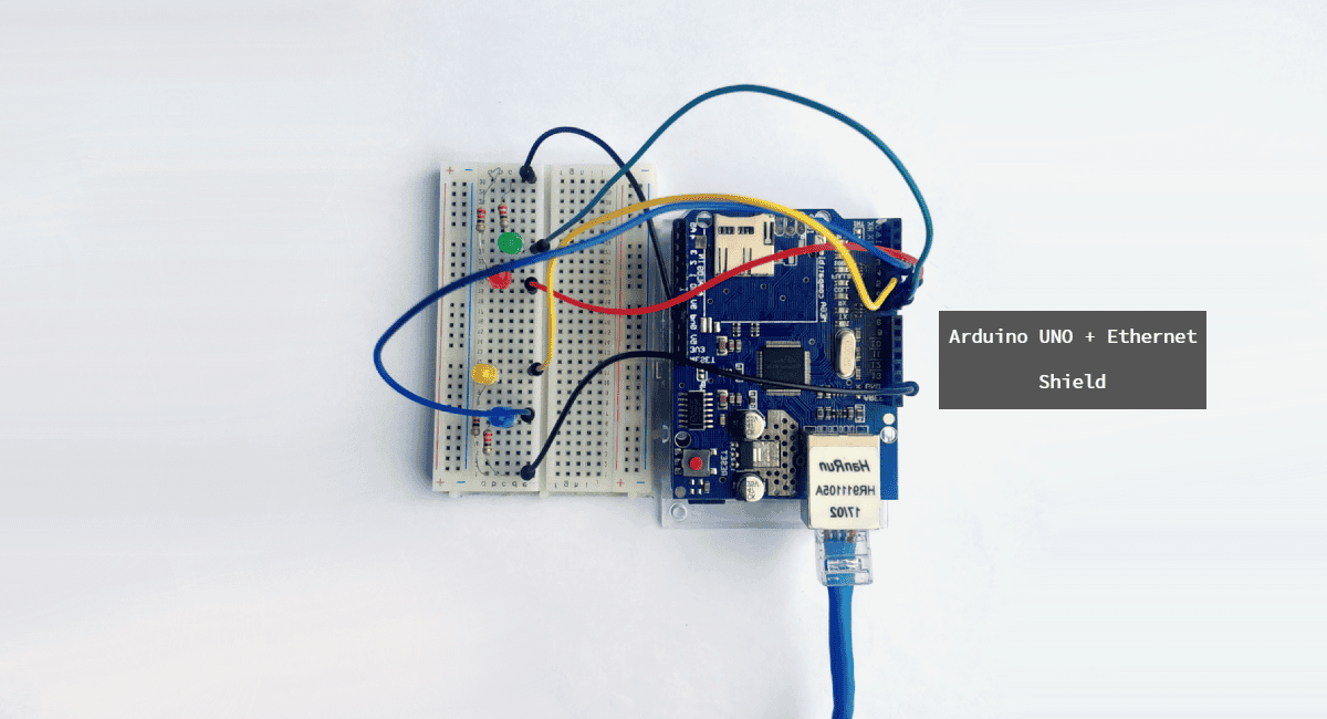
After assembling the components, plug a LAN cable into the RJ45 connector on the Ethernet shield. Connect the other end of the LAN cable to an internet connected router.
The Code
After connecting everything, upload this code to the Arduino:
#include <SPI.h>
#include <Ethernet.h>

byte mac[] = { 0xDE, 0xAD, 0xBE, 0xEF, 0xFE, 0xED }; //physical mac address
byte ip[] = { 192, 168, 0, 150 }; // IP address in LAN – need to change according to your Network address
byte gateway[] = { 192, 168, 0, 1 }; // internet access via router
byte subnet[] = { 255, 255, 255, 0 }; //subnet mask
EthernetServer server(80); //server port

String readString;
int ledPin = 2;

void setup(){

    pinMode(ledPin, OUTPUT); //pin selected to control
    // Test LED
    digitalWrite(ledPin, HIGH); // set pin high
    delay(500);
    digitalWrite(ledPin, LOW); // set pin low

    //start Ethernet
    Ethernet.begin(mac, ip, gateway, subnet);
    server.begin();
}

void loop(){
    // Create a client connection
    EthernetClient client = server.available();
    if (client) {
        while (client.connected()) {
            if (client.available()) {
                char c = client.read();

                //read char by char HTTP request
                if (readString.length() < 100) {
                    readString += c;
                }

                if (c == 0x0D) {
                    client.println("HTTP/1.1 200 OK");
                    client.println("Content-Type: text/html");
                    client.println();

                    client.println("<HTML>");
                    client.println("<HEAD>");
                    client.println("<TITLE> ARDUINO ETHERNET SHIELD</TITLE>");
                    client.println("</HEAD>");
                    client.println("<BODY>");
                    client.println("<hr>");
                    client.println("<hr>");
                    client.println("<br>");
                    client.println("<H1 style=\"color:green;\">ARDUINO ETHERNET SHIELD — LED ON/OFF FROM WEBPAGE</H1>");
                    client.println("<hr>");
                    client.println("<br>");

                    client.println("<H2><a href=\"/?LEDON\"\">Turn On LED</a><br></H2>");
                    client.println("<H2><a href=\"/?LEDOFF\"\">Turn Off LED</a><br></H2>");

                    client.println("</BODY>");
                    client.println("</HTML>");

                    delay(10);
                    client.stop();

                    // control arduino pin
                    if(readString.indexOf("?LEDON") > -1)
                    {
                        digitalWrite(ledPin, HIGH); // set pin high
                    }
                    else{
                        if(readString.indexOf("?LEDOFF") > -1)
                        {
                            digitalWrite(ledPin, LOW);
                        }
                    }
                    readString="";

                }
            }
        }
    }
}
Explanation of the Code
First, we need to include the required libraries. We will use SPI.h and Ethernet.h to communicate with the Ethernet shield. Both are already available in the Arduino core library so no need to install explicitly.
Next, we define the MAC address of the shield. The MAC address in the code is the default address for this type of shield. So if you’re using the same as mine, leave them as is. If you’re not confident, check your shield for a sticker with your MAC address. It’s normally on the bottom side.
Next, we use IPAddress ip(192, 168, 1, 99) and EthernetServer server(80) to establish a web server at port 80 with a static IP address of “192.168.1.99”. If you want to use a different IP, just change the values from that variable. Be sure to use an unused IP address, or else you will encounter networking problems.
In the loop function, we constantly check the status of the buttons on the webpage we created. Pressing the button on triggers a condition in the code which then turns on the LED using digitalWrite(). Then using print(), we send the HTML commands to the client.
Demonstration
Visit the static IP address (192.168.1.99) you set in the code in any web browser inside your network. It should show this and should update every five seconds as indicated in this line from the code client.println ("Refresh: 5").
Port Forwarding
Finally, to make the server available outside your home network, we need to employ port forwarding, Port forwarding is a network router feature that directs traffic from a particular port in your WAN to a device inside your LAN. Here’s how to do it:
- Find your WAN IP address. You can do this by simply typing “what is my IP address” into Google.
- Visit your router’s homepage. Enter your router’s gateway IP address in your web browser. Every model varies. For instance, my Hitron Technologies router uses “192.168.0.1”. On the home page, log in.
- Find out how to change the DHCP settings. You may need to search Google for instructions on how to do this for your particular model of router. Add the Ethernet shield’s IP Address to static so that it remains fixed. For our example server above, that would be “192.168.0.18”. Also, enter the MAC address you got from the AT+CIFSR command. After applying these, your router then reserves the 192.168.0.18 address to the Ethernet shield.
- Go to your router’s Port Forwarding settings. Create a virtual server using the TCP protocol. Use port 80 then enter the Ethernet shiled’s IP address. Don’t forget to save the changes you’ve made to your router.
- Configure your Firewall Settings to allow port 80 to communicate directly with your devices.
Be sure to leave a comment below if you have questions about anything!