One of the first uses of servo motors was to control the steering mechanisms of RC airplanes, cars, and boats. Today, you can find them in robots, industrial equipment, and many different Arduino projects.

Servo motors are capable of precise control of the rotation of a motor shaft. They allow you to set an exact angle of rotation with code, or with inputs like joysticks, push buttons, or potentiometers.
In this tutorial, we’ll take a look at how servo motors work and how to use an Arduino to control them. We’ll also look at two example programs you can run on the Arduino. The first program will show you how to control the direction and position of a servo using two push buttons. The second program will show you how to use a potentiometer to control the position of the servo.
Alright, let’s get started!
How Servo Motors Work
Servos are DC motors that have been geared down to reduce the speed and increase the torque of the motor. They also have built in circuits that control the angle of rotation one degree at a time, and hold that position until another input is received. Servos will rotate a certain number of degrees depending on the width of the electrical pulses delivered by the Arduino:
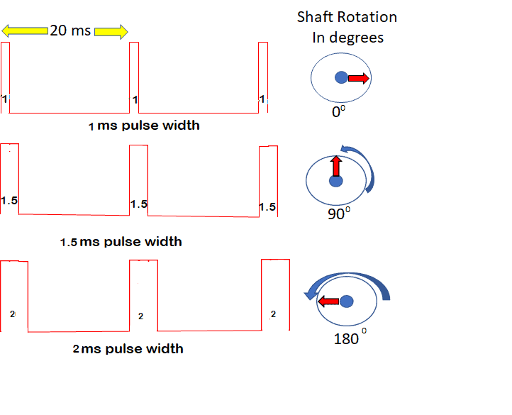
The servo expects one pulse every 20 ms. For most servos, a 1 ms pulse results in a zero degree rotation, a 1.5 ms pulse results in a 90 degree rotation, and a 2 ms pulse results in a 180 degree rotation.
Connecting the Servo Motor to the Arduino
Now let’s see how to use an Arduino to control a servo motor. These are the components you’ll need to setup the example projects discussed below:
- Arduino Uno
- SG90 Micro Servo
- 10K Potentiometer
- Resistors
- Capacitors
- 4X AA Battery Holder
- Tactile Push Buttons
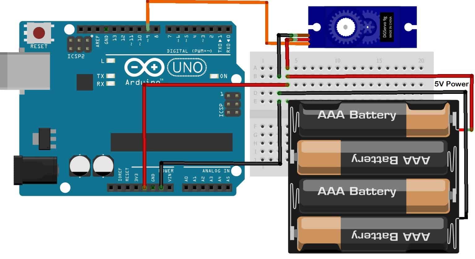
Depending on the servo you use (larger ones especially), you should use a separate DC power supply to power it. Otherwise, the current drawn by the servo could damage your Arduino.
If you want to learn more about the Arduino, check out our Ultimate Guide to the Arduino video course. You’ll learn basic to advanced Arduino programming and circuit building techniques that will prepare you to build any project.
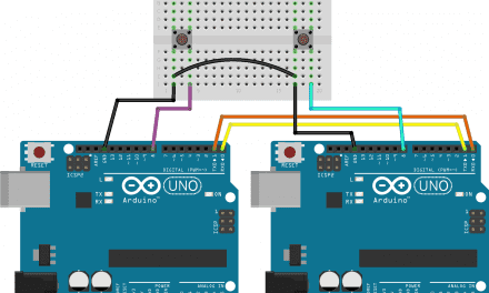
Once you have all of the components, connect them to the Arduino following this wiring diagram:

Programming the Servo
We’re going to use the Arduino’s built-in Servo library to program the servo. This library is included with the Arduino IDE, so there’s no need to install it.
Once you’ve connected the parts according to the wiring diagram above, open up the Arduino IDE and upload this code to the board:
#include <Servo.h>
Servo servo1;
int servoPin = 9;

void setup(){
  servo1.attach(servoPin);
}

void loop(){
  servo1.write(0);
  delay(1000);
  servo1.write(90);
  delay(1000);
  servo1.write(180);
  delay(1000);
}
The servo motor should move to 0 degrees, pause for one second, then move to 90 degrees, pause for one second, then move to 180 degrees, pause for one second, then start over.
On the first line we include the Servo library with #include <Servo.h>. On the next line, we create an object called servo1 to reference the specific servo motor throughout the code. On the next line, we declare a pin variable called serverPin and set it equal to Arduino pin 9.
In the setup section, we initialize the servo with the attach() function. The attach() function takes one parameter – the pin that the servo is connected to. So we have servo1.attach(servoPin).
To move the servo, use the write() function with the angle of rotation as the argument. The angle is in degrees, from 0 degrees to 180 degrees. The angle changes the pulse width sent to the servo motor, which then determines the amount of rotation. We’re calling the function through the servo1 object, so we use servo1.write(angle), with 0 degrees, 90 degrees, and 180 degrees.
The writeMicroseconds() Function
The write() function will work for most servos, but not all. Some servo motors have a range of 180 degrees, some have a range of 90 degrees, and some have anywhere in between. Using the write() function only allows for a maximum of 180 steps. However, there is a function that allows up to 1000 steps, called writeMicroseconds(). If you want more precise control of your servo, you may want to use the writeMicroseconds() function instead of write().
The sketch below demonstrates how to use the writeMicroseconds() function:
#include <Servo.h>
Servo servo1;
int servoPin = 9;

void setup(){
  servo1.attach(servoPin);
}

void loop(){
  servo1.writeMicroseconds(1000);
  delay(1000);
  servo1.writeMicroseconds(1500);
  delay(1000);
  servo1.writeMicroseconds(2000);
  delay(1000);
}
In this sketch, we’ve replaced each write() function with a writeMicroseconds() function. Change the angular values from (0, 90, 180) degrees to (1000, 1500, 2000) microseconds. Upload and run the program using the same hardware setup. For a servo motor capable of a range up to 180, the values will be 1000 microseconds = 0 degrees, 1500 microseconds = 90 degrees, and 2000 microseconds = 180 degrees.
Depending on the servo motor you are using, you may notice a difference. Interestingly on my setup, while monitoring the pulses on an oscilloscope, I noticed that when using servo1.write(0);, the pulse width was only about 700 microseconds, not 1000 which is the way the function should work when set at zero degrees. But when using servo1.writeMicroseconds(1000); the output was exactly 1000 microseconds.
Control a Servo With Push Buttons
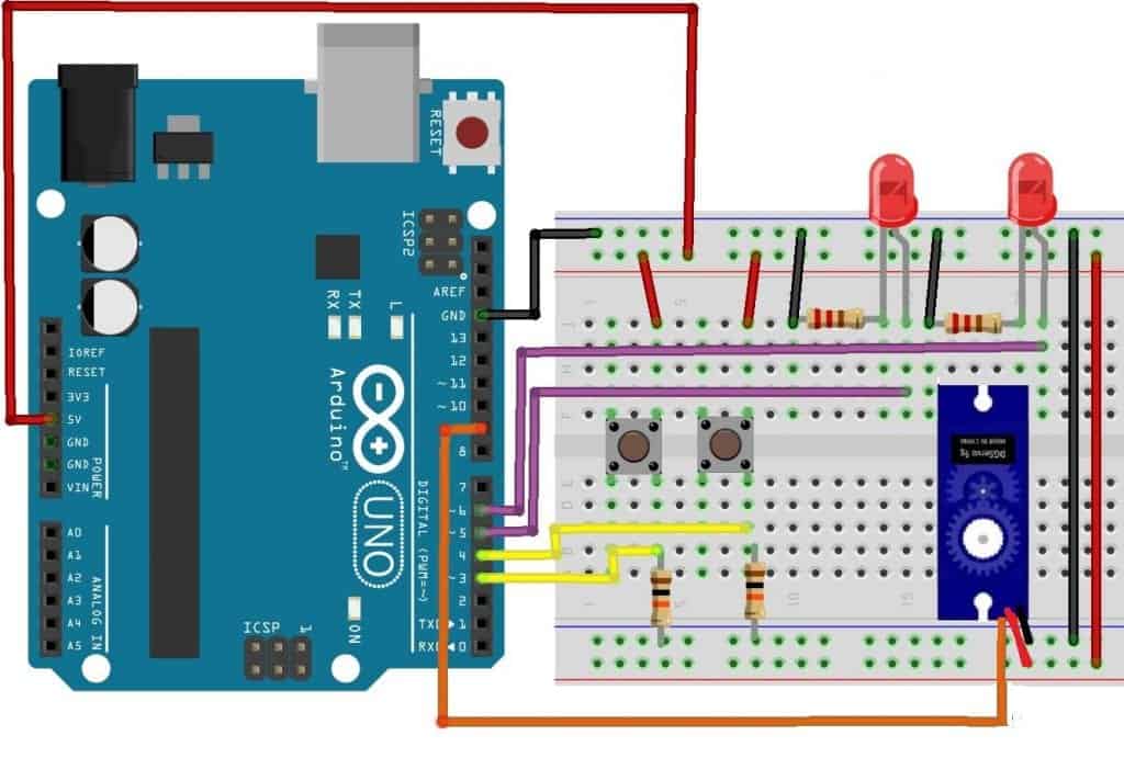
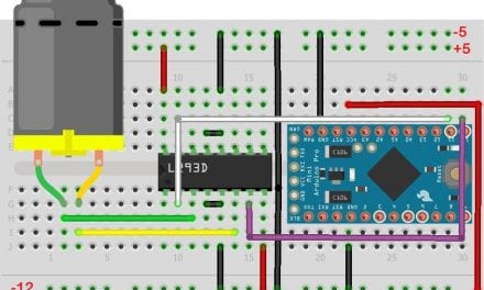
Build your circuit as shown in the diagram above, then upload the code shown below.
#include<Servo.h>
int pos = 90;
int pin4 = 4;
int pin3 = 3;
int LedHi = 5;
int LedLow = 6;
Servo servo1;

void setup() {
  pinMode(LedHi, OUTPUT);
  pinMode(LedLow, OUTPUT);
  pinMode(pin4, INPUT);
  pinMode(pin3, INPUT);
  Serial.begin(9600);
  servo1.attach(9);
}

void loop() {
  while (digitalRead(pin3) == HIGH && pos < 180) {
    digitalWrite(LedLow, LOW);
    pos++;
    servo1.write(pos);
    Serial.print("Degrees rotation= ");
    Serial.println(pos);
    if (pos == 180) {
      Serial.print("Reached top end ");
      digitalWrite(LedHi, HIGH);
    }
    delay(10);
  }

  while (digitalRead(pin4) == HIGH && pos > 0) {
    digitalWrite(LedHi, LOW);
    pos--;
    servo1.write(pos);
    Serial.print("Degrees rotation= ");
    Serial.println(pos);
    if (pos == 0) {
      Serial.print("Reached low end ");
      digitalWrite(LedLow, HIGH);
    }
    delay(10);
  }
}
After uploading the compiled code, open the Serial Monitor on your Arduino. As you push on either button, the servo should increase or decrease as shown on the serial monitor. Initially, the code will set the servo at 90 degrees. Use the button connected to pin 3 to increase the angle. When you reach 180 degrees, the high end of the rotation, the LED connected to pin 5 will turn on. When you reach the low end of the range which is 0 degrees, the LED connected to pin 6 will turn on.
To determine the result of the button push, a while statement verifies the button and the angle of the shaft. while (digitalRead(pin3) == HIGH && pos < 180) determines that the button was pushed (HIGH) and the angle is less than 180, so the program adds one degree and loops on. The second button while (digitalRead(pin4) == HIGH && pos > 0) determines that the button was pushed (HIGH) and the angle is greater than 0. This causes the angle to decrease by one and loops on. The LedHi and LedLow level for LEDs are each controlled by an if statement that checks the angle to see if it’s 0 or 180. The LEDs are turned off as soon as the angle changes in each of the two while statements.
Control a Servo With a Potentiometer
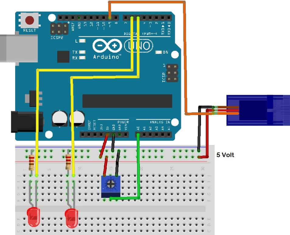
Build the circuit as shown in the diagram using a 10K potentiometer to control the servo motor. Then upload the code below.
#include <Servo.h>
int LowLed = 5;
int HiLed = 6;
Servo servo1;
int pot = A0;
int val;

void setup() {
  servo1.attach(9);
  pinMode(LowLed, OUTPUT);
  pinMode(HiLed, OUTPUT);
  Serial.begin(9600);
}

void loop() {
  val = analogRead(pot);
  val = map(val, 0, 1023, 0, 180);
  servo1.write(val);
  Serial.println(val);
  if (val == 0)
    digitalWrite(LowLed, HIGH);
  if (val == 180)
    digitalWrite(HiLed, HIGH);
  if (val > 0)
    digitalWrite(LowLed, LOW);
  if (val < 180)
    digitalWrite(HiLed, LOW);
  delay(10);
}
After uploading the code, open the serial monitor on your Arduino. As you adjust the potentiometer, the rotation of the servo will change accordingly. When you reach the lower limit of the range, the Low LED will turn on, and as you reach the upper limit, the High LED will turn on.
The code is straightforward. The first line of code in the loop() function should be:
val = analogRead(pot);
val = map(val, 0, 1023, 0, 180);
servo1.write(val);
analogRead() takes in the voltage from the potentiometer as an analog signal. It accepts the values of the full range of input accepted in an Arduino (0-5V). It captures it as an integer in the range of (0-1023). So for example, a DC value of 0V would be captured as the integer 0; a full range value of 5V would be captured as the integer 1023, and half the input range of 2.5V would be captured as the integer 512, half of 1023.
The next line of code val = map(val, 0, 1023, 0, 180); maps out the value of val within the range of 0, 1023, to a value of 0, 180.
The next line of code servo1.write(val); is the write() command that takes the integer stored in val as the argument and applies it to the servo. The servo receives a pulse from the servo1.write(val); and the pulse width is determined by the value of val. The servo uses the width of this pulse to determine its rotation.
Hope this helps you setup servos on the Arduino! Be sure to leave a comment below if you have questions about anything…


How can I control the servos pan and tilt with an auto-tracking moving camera ? I need help on this. Greatly appreciate it.
Servo drives are useful in many industries around the world, helping companies increase productivity and scale to a scale that people think is impossible.
Could you code circuit that rotates a servo from 0 Degrees To 90 To 180 then back to 90 when you push a button but keeps going on forever unless the button is pressed TO STOP THE SERVO BACK AT 0 DEGREES?
How does the servo motor gets the information or input to stop at the desired position?
I want to set up 2 mg 995 servo (0-90° continuous loop and 2 sg90 servo with 0-90° delayed for 5mins. How can I write code for this. I don’t know about coding. Please help if anybody can