
The Arduino’s GPIO pins are only capable of delivering a maximum current of 40 mA. Since even small 5V DC motors can draw 50 mA of current or more, it’s not recommended to drive DC motors directly from the Arduino’s GPIO pins. In this tutorial, we will discuss and learn about the following:

- Common issues in connecting and controlling a DC motor requiring high current
- How a Darlington transistor can be used to drive motors, relays, and solenoids with the Arduino
- How to control the speed of a DC motor using the TIP120 Darlington transistor and an Arduino
What’s the Problem With Inductive Loads?
Current flowing through a conductor creates a magnetic field around it. By wrapping the wire around an iron bar, you can create a rather strong electromagnet. DC motors have an internal permanent magnet with a coil of wire suspended inside the magnetic field of the permanent magnet. The coil, when energized, interacts with the permanent magnet causing it to spin. As the coil spins, it’s current stops then reverses direction through the coil which keeps it spinning. Every time current stops flowing through the coil, the electromagnetic field around the coil collapses back into the coils’ winding. The collapsing magnetic field induces a current flow in the opposite direction of the original current flow. This is referred to as back EMF. Back EMF needs to be addressed since the reverse current can damage the driving device.
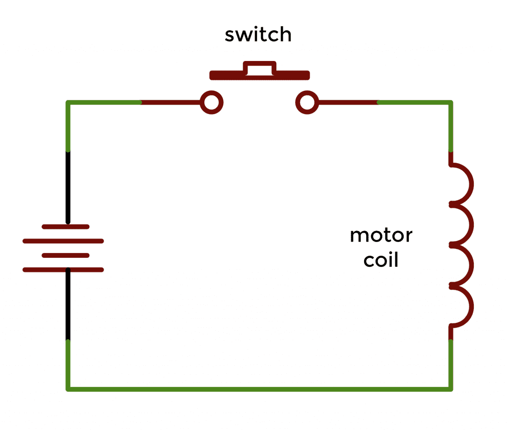
With the switch in the open position, no current flows through the coil:
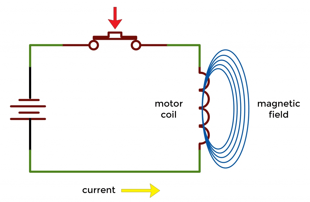
Closing the switch causes current to flow through the coil setting up a magnetic field (shown in blue) around the coil:
As soon as the switch is opened again, the magnetic field begins to collapse back into the coils. When a magnetic field cuts through a conductor, it induces a current in the opposite direction.
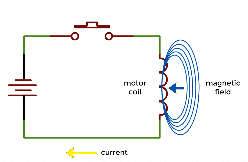
It’s this reverse current that can damage other devices connected to the same circuit.
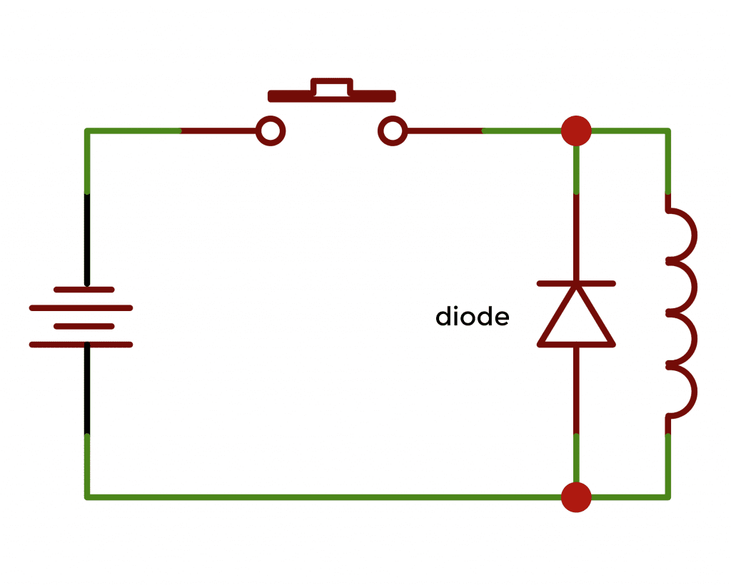
However, a diode placed across the motor windings will cause the reverse current to bypass the motor, helping to prevent back EMF.
Using a TIP120 Darlington Transistor to Drive a DC Motor
A Darlington transistor is mainly used to provide a very high current gain with a low base current.
How Does the TIP120 Work?
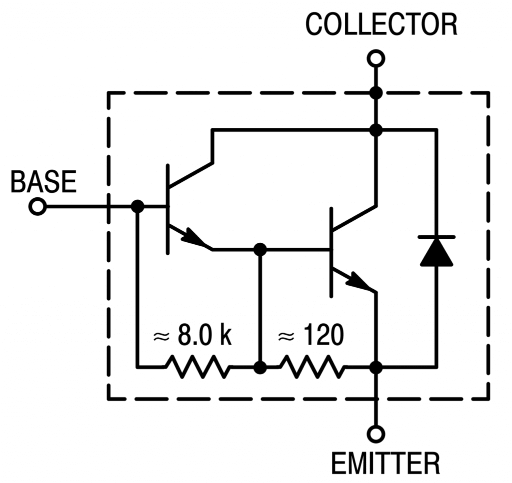
The TIP120 is a popular Darlington transistor because it’s low-cost, controls voltages up to 60V, and has a high voltage gain. The TIP120 has 2 NPN transistors and a large diode to prevent back EMF. Here’s a schematic of the internal circuitry of the TIP120:
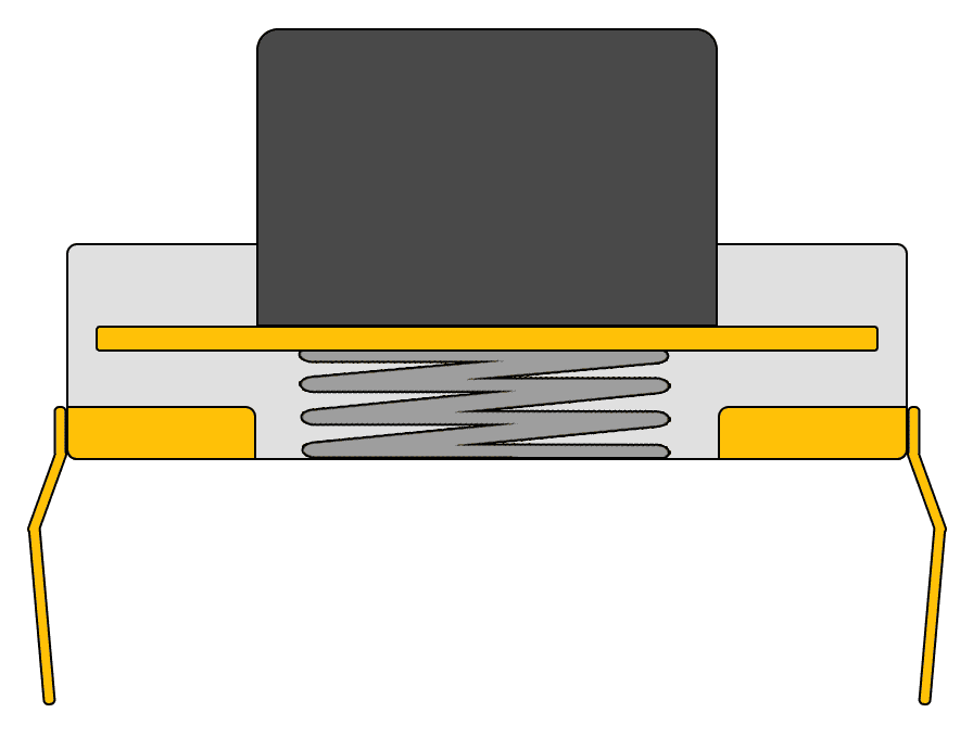
Here’s a pin diagram for the TIP120:

How to Connect a DC Motor and TIP120 to the Arduino
Let’s demonstrate how to use the TIP120 on the Arduino by building an example project that controls the speed of a DC motor with a potentiometer. To build this example project, you’ll need the following parts:
- Arduino Pro-Mini, or Arduino Uno
- TIP120 Darlington transistor
- DC motor (5-9 Volts)
- 2.2K resistor
- 330Ω resistor
- One LED
- 10K potentiometer
- 9V battery
- Jumper wires
- Small breadboard
Follow this wiring diagram to connect the DC motor and TIP120 to the Arduino:
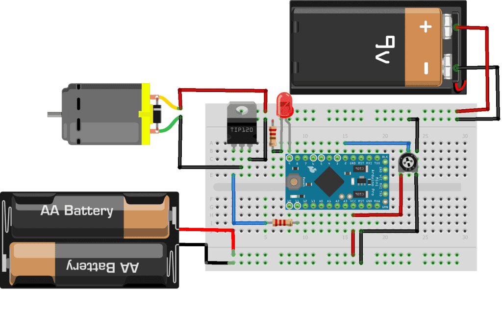
Note that the Arduino is powered by it’s own 3V power supply, while the DC motor is powered by a separate 9V battery.
If you need help getting started with the Arduino, check out our Ultimate Guide to the Arduino video course.
How to Program the DC Motor and TIP120 on the Arduino
After you’ve connected all of the parts as shown in the wiring diagram above, you’re ready to program the Arduino. Upload this code to the Arduino:
int speedSet = A0;
int Tip120 = 11;
int speedVal = 0;
int motorSpeed = 0;
int motorLimit = 0;
int LED = 9;

void setup() {
  pinMode(LED, OUTPUT);
  Serial.begin(9600);
}

void loop() {
  speedVal = analogRead(speedSet);
  motorSpeed = map(speedVal, 0, 1023, 0, 255);
  if (motorSpeed <= motorLimit)
  {
    digitalWrite(Tip120, LOW);
    digitalWrite(LED, HIGH);
  }
  else
  {
    digitalWrite(LED, LOW);
    analogWrite(Tip120, motorSpeed);
  }
  Serial.print("motorSpeed = " );
  Serial.print(motorSpeed);
  Serial.print(" motorLimit = ");
  Serial.println(motorLimit);
  delay(5);
}
Explanation of the Code
DC motors will run at voltages less than the rated voltage, but they will run inefficiently and can damage the motor. Therefore, we have added an indicator LED that will light up when the voltage is too low to power the motor. The value of motorLimit is initially set to zero.
After you upload the sketch above, open up the serial monitor and look at the motorSpeed value. This represents the power being sent to the motor. It will be a number between 0 and 255. Adjust the potentiometer until the motor is running smoothly (without any buzzing) and write down the motorSpeed value.
Now go back to the sketch and set the motorLimit variable equal to a number slightly greater than the motorSpeed value you wrote down. Then upload the sketch again, and you should see that the motor shuts off when the power is too low. The LED will also light up, indicating that the motor is off. This prevents the motor from starting until there is enough power for it to run properly.
If the motor is running too fast, create a high-speed cut-off by adding the variable int motorMax = xxx to the sketch above. Set xxx to whatever upper limit is necessary, up to 255. Then, on the line where it says if (motorSpeed <= motorLimit), change it to if (motorSpeed <= motorLimit || motorSpeed >= motorMax). The program will now cut off the motor at the lower and upper limits.
The sketch above uses the following variables:
speedSetis set equal to the analog pin (A0) that takes the input from the potentiometerTip120is set equal to the output pin that connects to the TIP120 transistorspeedValis used to store the value returned by theanalogRead()functionmotorSpeedis set equal to a number between 0 and 255, which will be passed to theanalogWrite()function to drive the motormotorLimitis set equal to a cutoff value that will be used to turn off the motor at slow speedsLEDis set equal to the pin connected to the indicator LED
In the sketch above, the variable speedVal will contain an integer from 0 to 1023, depending on the value output by the analogRead() function. It takes the analog voltage applied to speedSet (analog pin A0) and converts it into an integer stored in speedVal. In the next line, the map() function takes the value stored in speedValand converts it to a value between 0 and 255. The mapped value is stored in the motorSpeed variable. The motorSpeed variable is passed to the analogWrite() function later in the code to create a pulse width modulation (PWM) signal that is sent to the Tip120 pin.
The if statement performs a comparison to see if the motorSpeed variable is less than the motorLimit variable. If motorSpeed is less than motorLimit, Tip120 is set to LOW, turning off the motor and turning ON the LED indicator. Otherwise, the command analogWrite(Tip120, motorSpeed) sends the PWM signal to drive the motor with analogWrite(Tip120, motorSpeed);.
Hope this helps you to use DC motors in your own Arduino projects. If you have any questions, feel free to leave a comment below.


Do you need a diode for EMF protection?
The TIP120 has an internal diode for back EMF protection. An external diode isn’t needed.