In a previous article called How to Set Up a Web Server Using the Arduino and an ESP8266-01, we tackled the fundamentals of an Arduino web server. Now, let’s advance to learning how to control GPIO Pins. In this tutorial, we are going to toggle LEDs from a web page that can be accessed from any device with an internet connection.

But first, let’s review of some essential terms:
- Web server – a software, hardware, or combination of both that contains files needed to process and deliver web pages
- Web client – any device that can send an HTTP/web request to a web server
- Local server – a web server that can only be visited inside your LAN (Local Area Network)
- Global server – a web server that can be accessed anywhere via the internet
- HTTP POST – a web request that transmits data into the server
- HTTP GET – a web request that retrieves data from a web browser
- Port forwarding – a router setting that directs traffic from a WAN port to a particular device inside your LAN
Preparing the Hardware
For our sample project, you will need the following parts:
- Arduino Uno
- ESP8266 ESP-01 module
- 1 x 1kΩ resistors
- 2 x 2.2kΩ resistors
- 1 x 10kΩ resistors
- 1 x LED
- Breadboard
- Jumper wires
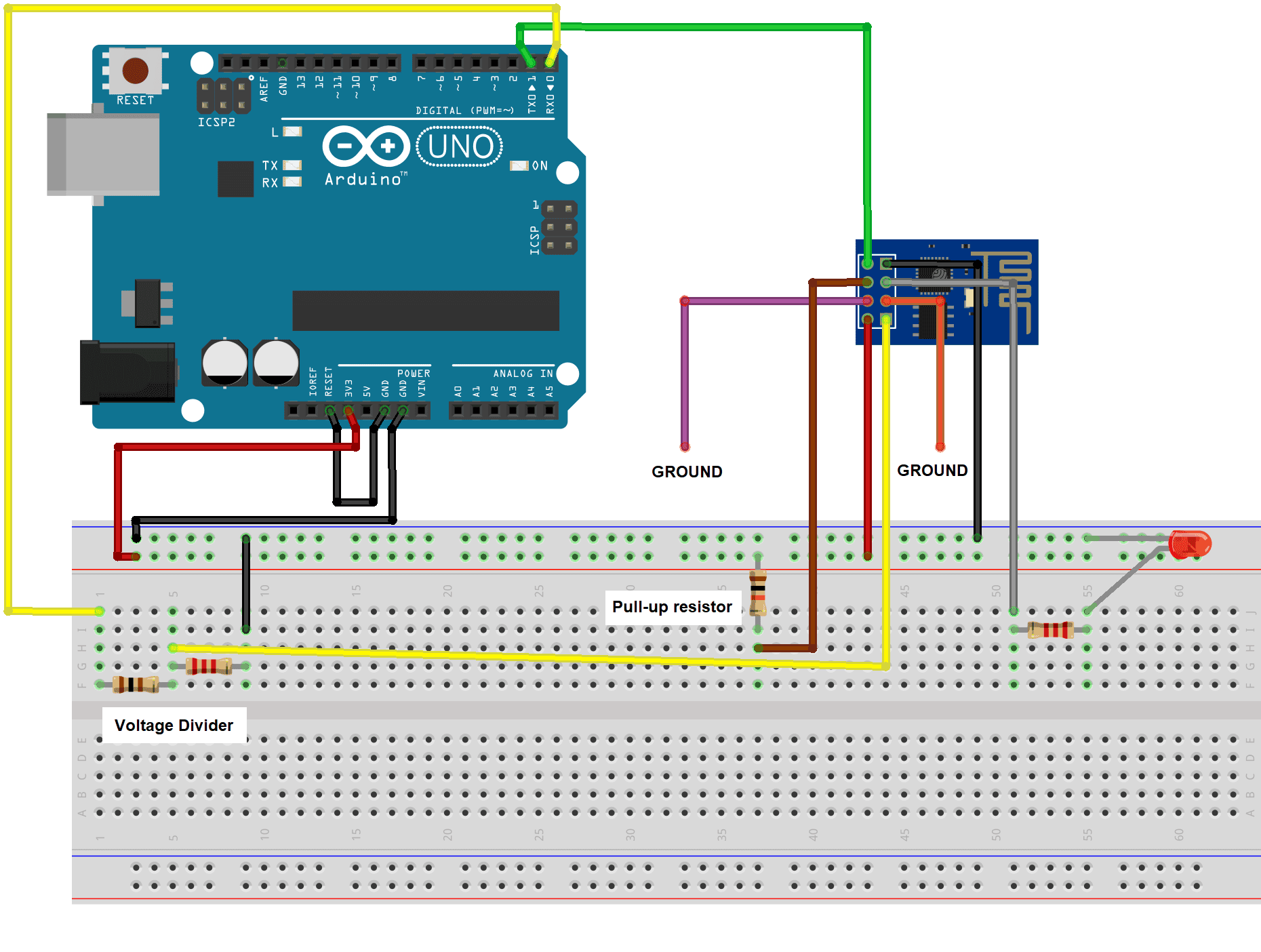
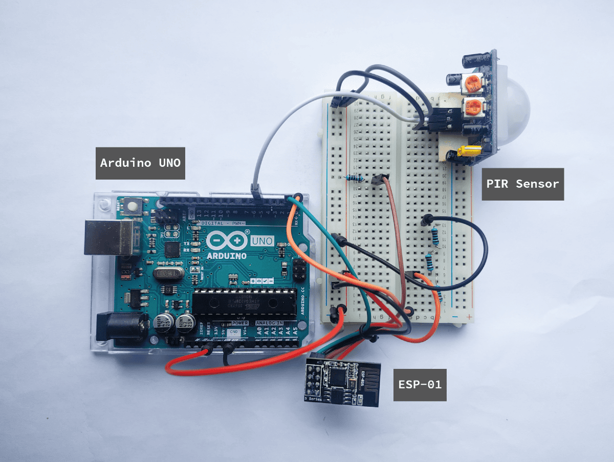
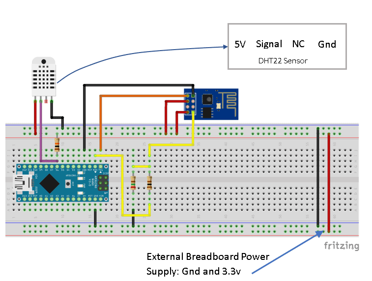
Using jumper wires, connect the parts as shown below:

If you want to learn more about the Arduino, check out our Ultimate Guide to the Arduino video course. You’ll learn basic to advanced Arduino programming and circuit building techniques that will prepare you to build any project.
Just like before, we are going to use an Arduino UNO to program the ESP-01 module. To do so, we will disable the UNO’s onboard chip by connecting the RESET pin to GND. Then, set the Generic ESP8266 module as your board in the Arduino IDE.
To set the ESP-01 module to program mode, connect the GPIO0 pin to GND. Similarly, connect and disconnect the RESET pin of the ESP-01 to the GND before uploading.
Troubleshooting Tips:
- Never forget to connect the Arduino RESET pin to GND.
- Make sure the upload speed is 115200.
- Check the voltage reading of your voltage divider circuit. It must give 3.3V to your RX pin.
- If you get constant errors uploading a sketch into the ESP-01, downgrade your ESP8266 board library in the Boards Manager to version 2.5.0.
- If the program doesn’t run after the upload, briefly connect then disconnect the ESP-01 reset pin to GND.
The Code
Copy the following sketch into the Arduino IDE.
#include <ESP8266WiFi.h>

const char* ssid = "WiFi name";
const char* password = "WiFi password";

int ledPin = 2;
WiFiServer server(80);

void setup()
{
  Serial.begin(115200);

  pinMode(ledPin, OUTPUT);
  digitalWrite(ledPin, LOW);

  Serial.print("Connecting to ");
  Serial.println(ssid);
  WiFi.begin(ssid, password);

  while (WiFi.status() != WL_CONNECTED)
  {
    delay(100);
    Serial.print(".");
  }
  Serial.println("");
  Serial.println("Connected to WiFi");
  Serial.print("IP: ");  Serial.println(WiFi.localIP());

  server.begin();
}

void loop()
{
  WiFiClient client = server.available();
  if (!client) {
  return;
  }

  while(!client.available()){
  }

  String request = client.readStringUntil('\r');
  Serial.println(request);
  client.flush();

  int value = LOW;
  if (request.indexOf("/LED=ON") != -1)
  {
    digitalWrite(ledPin, HIGH);
    value = HIGH;
  }
  if (request.indexOf("/LED=OFF") != -1)
  {
    digitalWrite(ledPin, LOW);
    value = LOW;
  }

  client.println("HTTP/1.1 200 OK");
  client.println("Content-Type: text/html");
  client.println(""); //  do not forget this one

  client.println("<!DOCTYPE HTML>");
  client.println("<html>");
  client.print("LED status: ");

  if(value == HIGH)
  {
    client.print("ON");
  }
  else
  {
    client.print("OFF");
  }
  client.println("<br><br>");
  client.println("Turn <a href=\"/LED=ON\">ON</a><br>");
  client.println("Turn <a href=\"/LED=OFF\">OFF</a><br>");
  client.println("</html>");

  Serial.println("");
}
Code Explanation
We only need the ESP8266WiFI.h this time. This comes with the ESP8266 board library so no need to install it.
#include <ESP8266WiFi.h>Enter your home network credentials here.
const char* ssid = "WiFi name";
const char* password = "WiFi password";
Set the webserver port number to 80.
WiFiServer server(80);In the setup section, set the LED pin as an output and initialize it to LOW.
Interestingly, the built-in LED of the ESP-01 is connected to GPIO2 but is active LOW. If you set the GPIO2 pin to LOW, the LED connected to GPIO2 turns off while the built-in LED lights up.
The setup also initializes the serial monitor. The serial monitor is used to display information like the ESP-01’s IP address. It also helps in identifying errors.
Lastly, the setup starts the webserver using server.begin().
void setup()
{
  Serial.begin(115200);

  pinMode(ledPin, OUTPUT);
  digitalWrite(ledPin, LOW);

  Serial.print("Connecting to ");
  Serial.println(ssid);
  WiFi.begin(ssid, password);

  while (WiFi.status() != WL_CONNECTED)
  {
    delay(100);
    Serial.print(".");
  }
  Serial.println("");
  Serial.println("Connected to WiFi");
  Serial.print("IP: ");  Serial.println(WiFi.localIP());

server.begin();
}
Next, in the loop section, we have server.available(). This function detects new web clients. It constantly returns false when there’s none. Conversely, the code proceeds to the next line if it detects a new client.
WiFiClient client = server.available();
  if (!client) {
  return;
  }
It waits until the client sends a request.
  while(!client.available()){
  }
And reads the request then prints it on the serial monitor. The client.flush() function makes sure all outgoing characters have been sent.
  String request = client.readStringUntil('\r');
  Serial.println(request);
  client.flush();
/LED=ON and /LED=OFF are the names of the requests that we are going to use to toggle the LED on and off. We will see them later in the HTML code. Basically, if the previous line reads /LED=ON, the program sends a HIGH to the LED pin and vice versa.
  int value = LOW;
  if (request.indexOf("/LED=ON") != -1) {
  digitalWrite(ledPin, HIGH);
  value = HIGH;
  }
  if (request.indexOf("/LED=OFF") != -1){
  digitalWrite(ledPin, LOW);
  value = LOW;
  }
Finally, we create a web page using client.println().
  client.println("HTTP/1.1 200 OK");
  client.println("Content-Type: text/html");
  client.println("");

  client.println("<!DOCTYPE HTML>");
  client.println("<html>");
  client.print("LED status: ");

  if(value == HIGH)
  {
    client.print("ON");
  }
  else
  {
    client.print("OFF");
  }
  client.println("<br><br>");
  client.println("Turn <a href=\"/LED=ON\">ON</a><br>");
  client.println("Turn <a href=\"/LED=OFF\">OFF</a><br>");
  client.println("</html>");

  Serial.println("");
Here, we see how we named the requests /LED=ON and /LED=OFF.
  client.println("Turn <a href=\"/LED=ON\">ON</a><br>");
  client.println("Turn <a href=\"/LED=OFF\">OFF</a><br>");
Demonstration
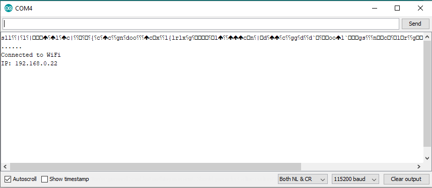
1. Upload the sketch, then open the serial monitor. There will be instances when the serial monitor displays garbage data and the ESP-01 refuses to connect. An easy fix would be briefly connecting and disconnecting the ESP-01 RESET pin to the ground.
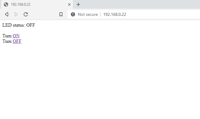
2. Enter the given IP address from the serial monitor to any web browser. The first line indicates whether the LED is currently turned ON or OFF. To change it, simply click the links.
Let us know how it goes in the comments!


Very good tutorial. Would love to see more like this.
But your title is slightly misleading to the viewers. Your title says we will control Arduino’s GPIO pins using esp8266, while in reality, we are controlling esp8266’s GPIO pins only.
Thank you so much for this good post. It is realy helpful.
Could do you please improve the project by making the gpio pins accessible from anywhere over the internet???