
In this tutorial, we will see how to use sensor data to control a 5V relay connected to an Arduino. We will build a sample project that will turn on/off a lamp when the reading from a photoresistor crosses a threshold value. The project will also be able to turn a lamp on and off with a variable timer.

For this project, we need the following components:
- Arduino Pro-Mini, or Arduino Uno
- SRD-05VDC-SL-C 5V relay
- Photoresistor
- 10K resistor
- 10K potentiometer
- Breadboard
- Jumper wires
- A/C power cord
- Light socket
- LED (optional)
- 330 Ohm resistor (optional)
But first, let’s review some concepts!
Relays
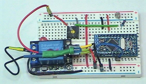
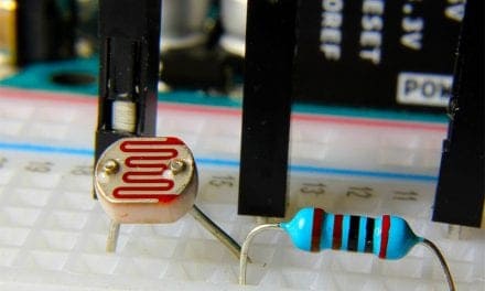
Relays are electromechanical devices used to control power for the attached devices. With a relay, you can easily use an Arduino to control the power of nearly any type of electrical device. The circuit shown below uses an LED as the output device.
Relays are often used in home automation projects. They can be configured to switch AC line current to loads like fans, motors, and lights.
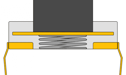
How Relays Work
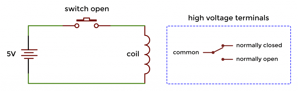
Inside the relay is an electromagnetic coil that actuates a high voltage switch when there is current flowing through the circuit.
With no current flowing through the coil, the relay is in the normally closed position:
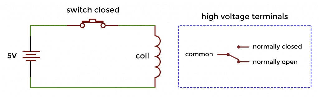
When the switch is closed, current flows through the coil and the electromagnetic field produced from the coil causes the high voltage terminal to switch to the normally open position:
When working with inductive loads like relays, solenoids, motors, or stepper motors, it’s important to protect your circuit against back EMF. Back EMF happens when the electromagnetic field surrounding the coil collapses back into the coil. This induces a large reverse current in the coil, which can damage other components in the circuit. To prevent back EMF, a diode needs to be placed in parallel with the coil.
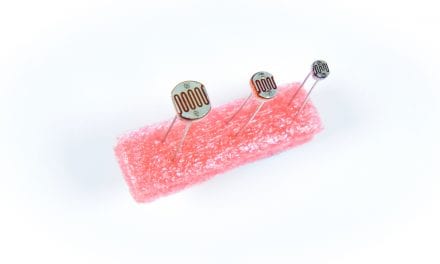
Photoresistors
Photoresistors or Light Dependent Resistors (LDR) are light sensing devices. In bright light, a photoresistor has a lower resistance. As the light gets dimmer, the resistance increases. The typical range of a photoresistor runs from about 3K ohms in high light levels to many Mega ohms in low light levels.
You can check the resistance of the photoresistor in low and high light levels with an ohm meter. Keep in mind that two identical photoresistors may have different resistance ranges.

Controlling Lights Using a Relay and Arduino
Now, connect the components to build the circuit as shown below:
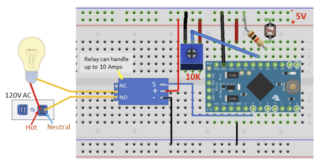
Note: The relay has a built-in transistor to drive the relay coil as well as a diode across the winding to protect the transistor. Since the relay can draw as much as 80 mA when energized, you could damage the Arduino if you drive the relay directly from it.
The Code
After everything is connected according to the wiring diagram above, upload this code to your Arduino:
const int photoResistor = A0;
const int pot = A1;
const int relay = 3;
bool timer = false;
int val = 0;
int val0 = 0;
int bright = 5;
const float wait = 144000;

void setup() {
  pinMode(relay, OUTPUT);
}

void loop() {
  val0 = analogRead(pot);
  val0 = map(val0, 0, 1023, 0, 100);
  val = analogRead(photoResistor);
  val = map(val, 0, 1023, 0, 100);
  if ((val <= bright) & (val0 == 0) & (timer == false))
  {
    digitalWrite(relay, HIGH);
  }
  else if ((val <= bright) & (val0 > 0) & (timer == false))
  {
    digitalWrite(relay, HIGH);
    delay(wait * val0);
    timer = true;
    digitalWrite(relay, LOW);
  }
  else if (val >= bright)
  {
    digitalWrite(relay, LOW);
  }
  if (( val > 15) & (timer == true))
    timer = false;

}
How the Code Works
After uploading and compiling the code, set the 10K potentiometer to the minimum. The relay will turn on the light when the photoresistor is dark (covered). And when the control is set to minimum, the relay turns on the light then off as soon as light returns (sunset to sunrise).
However, if you want the light to come on at dark, stay on for a while, then turn off before sunrise. Adjust the 10K potentiometer to control how long the light stays on after dark. The timer is activated as soon as the timing control is turned above 0V (zero volts).
Turning up slightly the timing control will turn the lights on for a few minutes before turning off again. When you turn up the control in full, the light will stay on for approximately 4 hours before turning off. Everything automatically resets after timing has expired and light is available. By turning the control all the way down (to zero volts), the light comes on at dark and stays on until light returns (sunset to sunrise). If you need to manually reset the device, consider adding a pushbutton switch to ground the reset button (RST).
Timer and Timing
The timer’s range can be adjusted up or down from 14400 using the variable wait. It is approximately 4 hours when at maximum. You can also adjust the light level that triggers the relay. The variable bright was initially set to 5. But by raising this value, the lights will activate at a higher light level. On the other hand, lowering its value would make the room go darker before the lights go up. However, remember to not set the bright value higher than 14.
Timing is based on the delay function that works in milliseconds. The timing potentiometer presents an analog input read into the variable val0. It is then transformed with the map function to a range of 0 to 100. You can try and vary the range to (0-50) with this code val0 = map(val0, 0, 1023, 0, 50); or (0-250) with this val0 = map(val0, 0, 1023, 0, 250);.
Position the photoresistor so it is not directly in line with the light when it comes on. You can adjust the sensitivity of the photoresistor as mentioned earlier with the bright variable. Be sure to leave a comment below if you have questions about anything!


A really cool way to help teenage boys electrocute themselves.
Where would the optional 330 ohm resistor be inserted in the circuit, and why would one place it there?