In this tutorial, we will discuss how stepper motors work, and how to use the ULN2003 stepper motor driver to control the stepper motor’s number of revolutions, speed, steps, and direction with an Arduino. We will also compare uni-polar and bi-polar stepper motor configurations, and discuss stepper motor power requirements.

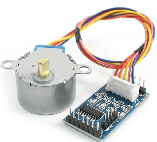
Using the 28BYJ-48 stepper motor we will create a circuit to demonstrate the basic setup of a stepper motor. Then we will control the stepper motor’s speed with a potentiometer. The last project will show you how to control a stepper motor’s direction with the push of a button.
How the Stepper Motor Works
Stepper Motors are used when precise control of the rotating shaft is required. A good example would be a robotic arm that reaches out for a component, picks it up, and places it exactly where it’s needed.
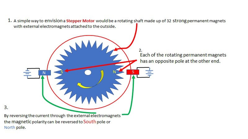
Stepper Motors are brushless DC motors with the shaft attached to a series of permanent magnets that control the shaft rotation to 32 equal steps. The shaft is connected to a series of gears to reduce its speed and increases the torque of the motor. In a 28BJY-48, these gears reduce the speed by a factor of 64. So the motor shaft must rotate 32 times to get 1 full rotation of the shaft, which then rotates 64 times to get 1 full revolution of the stepper motor.
Utilizing a ULN2003 driver and an Arduino UNO, or Arduino Pro-Mini, provides precise timing, directional control, and power management for the stepper.
There are two types of stepper motor configurations: the uni-polar and the bi-polar. Each has specific attributes to consider when designing a device using stepper motors.
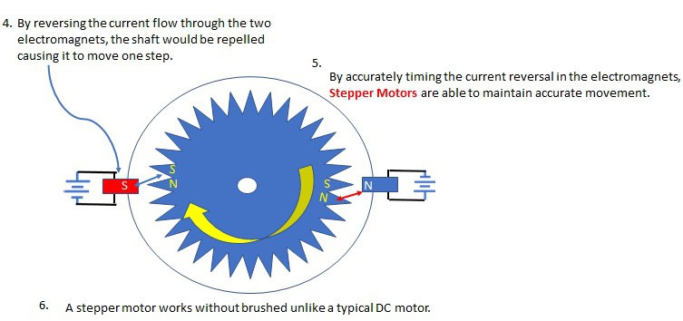
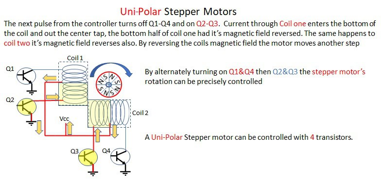
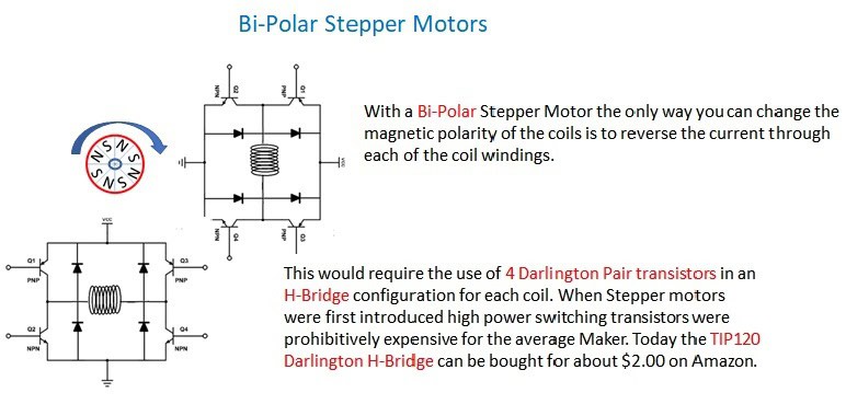
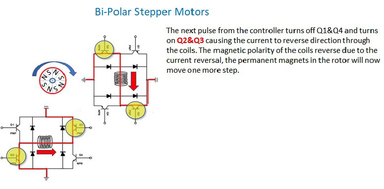
In order for the stepper motor to move to the next step, reverse the current through the electromagnets.
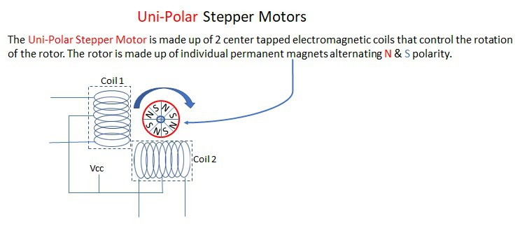
Unipolar and Bipolar Stepper Motors
Each of the two basic configurations of the stepper motor, unipolar and bi-polar, have specific differences that in the past were important due to the high cost of switching transistors. Today, with low-cost Darlington pair transistors readily available, the cost-benefit of a unipolar stepper motor has lost some of its early appeals.
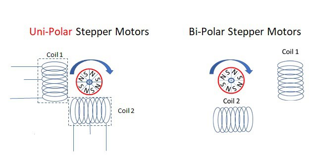
Each of the configurations above utilizes a rotating shaft made up of numerous powerful permanent magnets.
Connect two transistors to each coil to control the current through the coil windings.
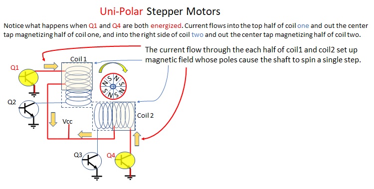
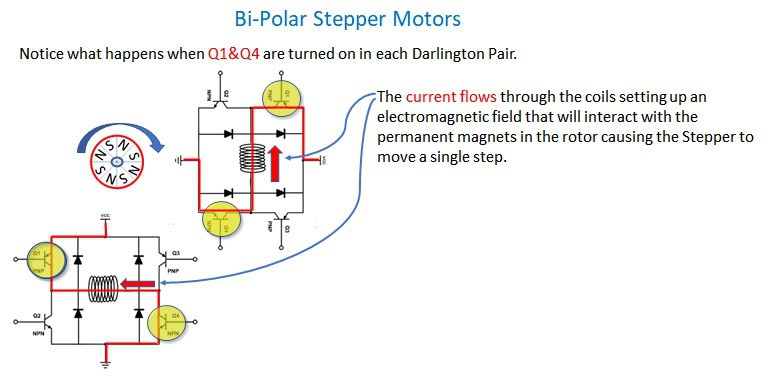
By controlling the direction of current flow through the driving transistors, the rotation of the stepper motor can be easily controlled.
“Half-step” and “full-step” are methods by which stepper motors control their output. It configures the driving transistors slightly differently using two motors simultaneously, as discussed in the bi-polar example. Half-step moves the stepper half the distance but uses more power since you are using two motors, or in the case of unipolar, you’re using the full capacity of both coils. The benefit of half-step is that smaller steps give you more control, more accuracy, and more torque. The disadvantage is that you are consuming more power than you would in full-step.
A 28BYJ-48 Stepper Motor is configured to create a total of 32 full steps in one revolution (32:1 ratio). It is then connected to a series of gears that further reduces the speed and increases the torque (64:1 ratio). The motor must step 32 times for its shaft to rotate once and the shaft must then rotate 64 times for the gear reduction to cause the stepper motor to rotate once.
ULN2003 Stepper Motor Driver
The 28BYJ-48 Stepper Motor can draw up to 240 mA, considerably more than what an Arduino can deliver through any of its ports. So, you will need some sort of a driver to safely control the stepper motor. There are numerous ways to create a driver starting with a simple transistor for each of the coils. This solution would also require clamping diodes to protect the Arduino from the inductive voltage induced from the coil.
There are prefabricated circuits that incorporate the ULN2003 integrated circuit. You could also use just the ULN2003 integrated circuit rated at 500 mA at 50V which is a little cheaper than the prefabricated PCB. Since the prefabricated circuit board and the ULN2003 connections are nearly identical, for this tutorial we will just use the integrated circuit.
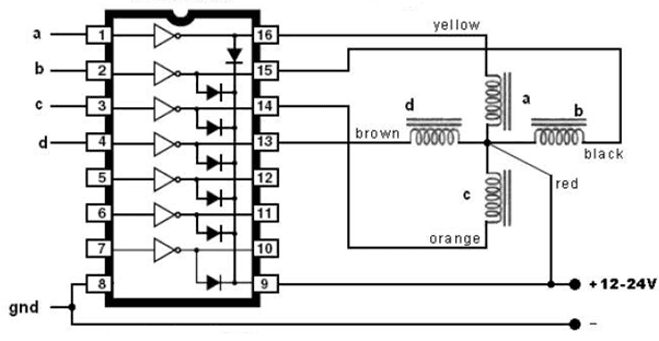
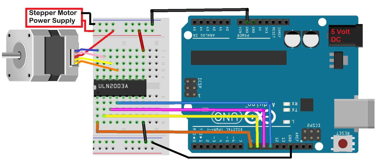
The above diagram shows the ULN2003 connected to the 28BYJ-48 stepper motor. Pin 9 of the ULN2003 supplies the voltage for the stepper motor while pins 1-4 are connected to the Arduino.
Setting Up the Stepper Motor
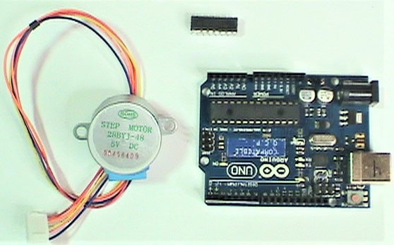
Components needed for the example projects below:
- Arduino UNO
- 28BYJ-48 stepper motor
- Push button switches (2)
- ULN2003 stepper controller
- Breadboard
- Jumper wires
- 10K potentiometer
- LEDs (2)
- 220 Ohm resistors (2)
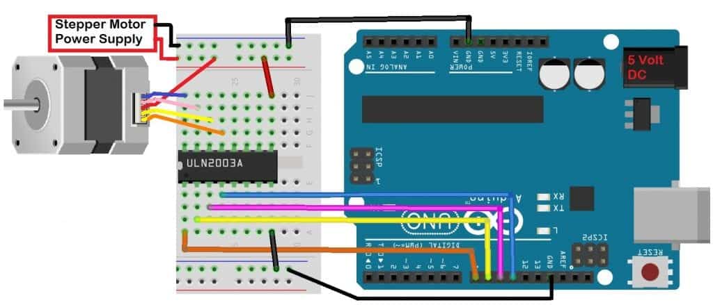
Now that we understand how to control the actions of the stepper motor, start assembling the circuit according to this wiring diagram:
If you want to learn more about the Arduino, check out our Ultimate Guide to the Arduino video course. You’ll learn basic to advanced Arduino programming and circuit building techniques that will prepare you to build any project.
How to Program the Stepper Motor
Upload this code to the Arduino:
#include <Stepper.h>
const int stepsPerRevolution = 2048;
const int rpm = 6;
Stepper stepper1 = Stepper(stepsPerRevolution, 8, 10, 9, 11);

void setup() {
  stepper1.setSpeed(rpm);
}

void loop() {
  stepper1.step(stepsPerRevolution);
  delay(100);
  stepper1.step(-stepsPerRevolution);
  delay(100);
}
After compiling and uploading the code, the stepper motor should do one complete clockwise revolution in 10 seconds. Then, it reverses direction and complete a counter-clockwise rotation in 10 seconds.
Explaining the Code
The first entry is the <Stepper.h> library that facilitates control of the stepper motor followed by the creation of two variables: stepsPerRevolution, and rpm.
The next one creates a stepper motor object using the library to reference the specific stepper motor. In our example, we used “stepper1”, that’s why it has to be Stepper stepper1 = Stepper(stepsPerRevolution, 8, 10, 9, 11);. The function uses 5 variables, the number of steps per revolution, as well as the 4 ports used to connect the Arduino to the driver.
For the setup() function, setSpeed(), stepper1.setSpeed(rpm); was used to indicate the speed of the motor’s shaft with the variable rpm set up earlier.
For the loop() function, we used the step() function to indicate the total number of steps in a revolution. Since the stepsPerRevolution variable was already set up earlier, we used stepper1.step(stepsPerRevolution); followed by a delay(), then reversed the direction of the stepper with the step() function again.
Demonstration
- Set the
stepsPerRevolutionto 200, and the rpm to 1. - Then run the modified code while touching the stepper motor (it will probably be warm to the touch). See if you can feel the steps as the stepper turns. 200 steps at 1 rpm will cause the motor to move almost imperceptibly, but you will feel the motor stepping.
- Change the rpm to 10 and steps set to 2048 and try it again. You can think of
stepsPerRevolutionas distance and rpm as speed. - Try different variations of rpm and steps. RPM ranges from (1-16), Steps range from (20 – 2048).
There are some issues with stepper motors like users have no options where to set the stepper to begin without elaborate hardware additions. It will start at the same spot where it has completed the last revolution. If you need to specify the starting position, you should consider using a Servo Motor.
Controlling the Stepper Motor Speed with a Potentiometer
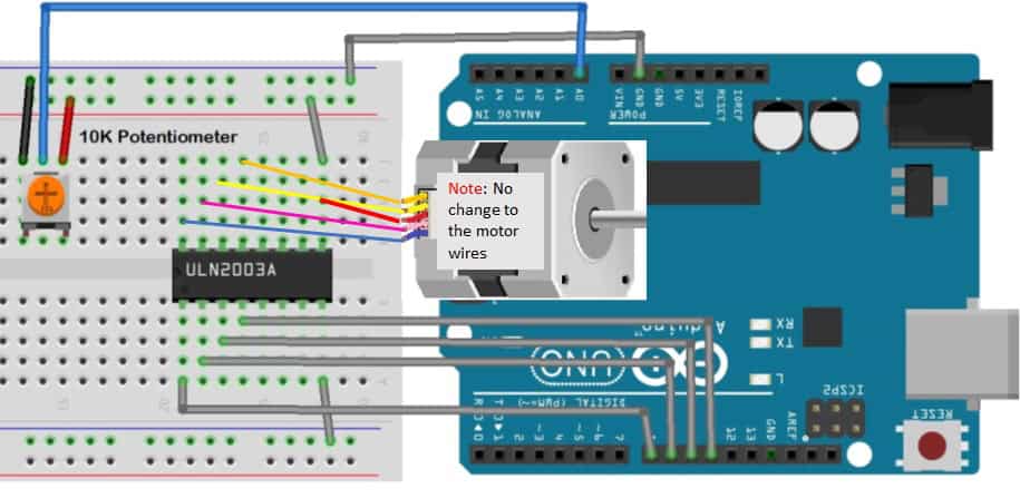
Once the circuit is connected, upload this code to the Arduino:
#include <Stepper.h>
const int stepsPerRevolution = 200;
Stepper stepper1(stepsPerRevolution, 8, 9, 10, 11);

void setup() {}

void loop() {
  int potReading = analogRead(A0);
  int motorSpeed = map(potReading, 0, 1023, 0, 100);
  if (motorSpeed > 0) {
    stepper1.setSpeed(motorSpeed);
    stepper1.step(stepsPerRevolution / 100);
  }
}
After adding the rather simple code, upload it to your Arduino. The speed of the stepper motor will now be controlled by the potentiometer.
The output from the potentiometer is read into analog port A0. In the next line, the integer stored in potReading should be within the range of (0-1023) determined by the voltage read at A0. This integer is mapped into the variable motorSpeed as an integer with a value of (0-100). This is used with the setSpeed() function to control the stepper.
Controlling Speed and Direction with Push Buttons
While the <Stepper.h> function is nice to have, it does not allow you to easily reverse directions on-demand with the push of a button. To do that, you will need to control each coil directly.
Build the circuit below to allow direction control with push buttons:
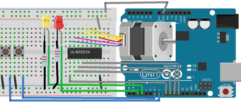
Once the circuit is connected, upload this code to the Arduino:
const int IN1 = 8;
const int IN2 = 9;
const int IN3 = 10;
const int IN4 = 11;
const int upButton  = 6;
const int downButton = 7;
const int ledUp  = 2;
const int ledDown = 3;

int coil1[] = {0, 0, 0, 0, 0, 1, 1, 1, 0};
int coil2[] = {0, 0, 0, 1, 1, 1, 0, 0, 0};
int coil3[] = {0, 1, 1, 1, 0, 0, 0, 0, 0};
int coil4[] = {1, 1, 0, 0, 0, 0, 0, 1, 0};

int coilStep = 0;
int rotation = 3;

void setup()
{
  pinMode(IN1,OUTPUT);
  pinMode(IN2,OUTPUT);
  pinMode(IN3,OUTPUT);
  pinMode(IN4,OUTPUT);
  pinMode(ledUp,OUTPUT);
  pinMode(ledDown,OUTPUT);
  pinMode(upButton,INPUT_PULLUP);
  pinMode(downButton,INPUT_PULLUP);
}

void loop()
{
  if (digitalRead(upButton) == LOW)
  {
    rotation = 1;
  } else if (digitalRead(downButton) == LOW)
  {
    rotation  = 2;
  } else
  {
    rotation = 3;
  }
  if (rotation == 1) {              // Forward
    digitalWrite(ledUp, HIGH);
    coilStep++;
    motorDrive(coilStep);
  }
  else if (rotation == 2) {       // Reverse
    digitalWrite(ledDown, HIGH);
    coilStep--;
    motorDrive(coilStep);
  }
  else {
    motorDrive(8);
    digitalWrite(ledUp, LOW);
    digitalWrite(ledDown, LOW);
  }
  if (coilStep > 7) {
    coilStep = 0;
  }
  if (coilStep < 0) {
    coilStep = 7;
  }
  delay(10);
}

void motorDrive(int d)
{
  digitalWrite(IN1, coil1[d]);
  digitalWrite(IN2, coil2[d]);
  digitalWrite(IN3, coil3[d]);
  digitalWrite(IN4, coil4[d]);
}
After compiling and loading the program, the buttons will control the direction of the stepper motor. The two LEDs indicate the direction of rotation.
Explaining the Code
Notice here that we did not include the <Stepper.h> library since we have to reverse the stepper motor’s direction on-demand (button push). We need to control it differently. We used an array to control each coil. The use of arrays greatly simplifies the code required. In int coil1[] = {0, 0, 0, 0, 0, 1, 1, 1, 0};, the first array is what controls the first coil. To identify an array, use the name of the array and the position of the item you want.
In programming norms, counting starts with 0, not 1. So the first entry in an array would be array_name[0]. Notice also the use of the function motorDrive() created to drive each coil. When the function motorDrive() is called, it passes the value of coilStep into the function as an integer d. This is used with digitalWrite(IN1, coil1[d]); the first time it’s called, coilStep is “0”. Remember that 0 is the first value in the array we call coil1. The first entry in the array coil1[] is the integer 0, so the IN1 is driven low.
The function continues to digitalWrite(IN2, coil2[d]); since the integer d is still 0. The first element in the array coil2[] is the integer 0 . When the function motorDrive completes the program, it returns to where it was when the function was first called.
If the upButton is still depressed, the variable coilStep is incremented by 1. If the downButton is depressed, the variable coilStep is reversed. If no buttons are pressed, the function motorDrive sends the integer 8. The eighth entry in all the arrays are low, stopping the stepper motor and the function goes on.
Let us know how this goes! Feel free to leave a comment below with any questions.


thanks for explainings
Hi, great article, however I think your code is flawed as you increment coilStep and then use it as an array index, but only later do you check that the index was with in the bounds of the array. For example, coilStep = 7. the code adds 1, then calls motorDrive() with 8 as the parameter which stops the motor, only later does the code check that coilStep is great than 7 and resets it to 0. The reverse case is worse, coilStep is 0 (initial value), and reverse is pressed so coilStep– gives us -1 and then motorDrive(-1) before check that -1 < 0 and setting it to 7.
I hooked it up according to the schematic and uploaded the code. Nothing happened. Thought i might had reversed the diodes, so i switched polarity on one of them an now the motor turns CW with one button (both diodes light up) and the other button makes it go CCW ( no diodes light up). So my circuit is the same apart from one of the diodes being reversed. How is this possible ?