PS2 joysticks are great for controlling things like motors and servos, and they can also be used to navigate through menus on LCDs or other displays. In this article, we will see how to read the raw output from a PS2 joystick, then take that reading and use it to control other devices with an Arduino.

We’ll build an LED controller that will fade on and off a set of LEDs with pulse width modulation (PWM) when you move the joystick. We’ll also learn how to use the map() function to convert one range of values to a larger or smaller range of values.
Watch the video for this tutorial here:
Overview of a PS2 Joystick
The PS2 joystick we will use in this article is a Keyes KY-023 joystick:
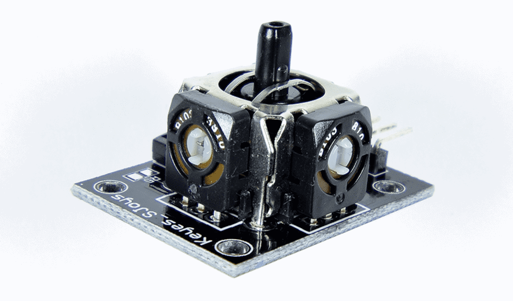
PS2 joysticks have two potentiometers and a push button. One potentiometer is attached to the X axis, and the other potentiometer is attached to the Y axis. When you push the joystick in one direction, the resistance of the potentiometer changes and outputs a varying analog voltage. We can detect this voltage with the Arduino to determine the position of the joystick.
The push button switch creates a low digital signal when the joystick is pushed down.
There are five pins on the Keyes KY-023 joystick:
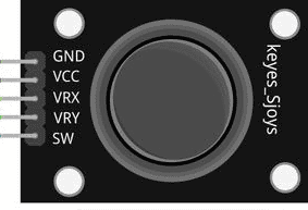
- GND – connects to the Arduino’s ground pin
- VCC – connects to the Arduino’s 5V pin
- VRX – the X axis analog signal output
- VRY – the Y axis analog signal output
- SW – the push button digital output
How PS2 Joysticks Work
The signals output by the X and Y axis potentiometers are analog signals, so we will use the Arduino’s analogRead() function to get the readings from the joystick. The analogRead() function takes a voltage reading from the analog pins and converts it to a number between 0 and 1023. A 0 corresponds to 0 volts, and a 1023 corresponds to 5 volts. When the joystick is centered, the analogRead() value from each axis will be close to half of 1023, or about 511:
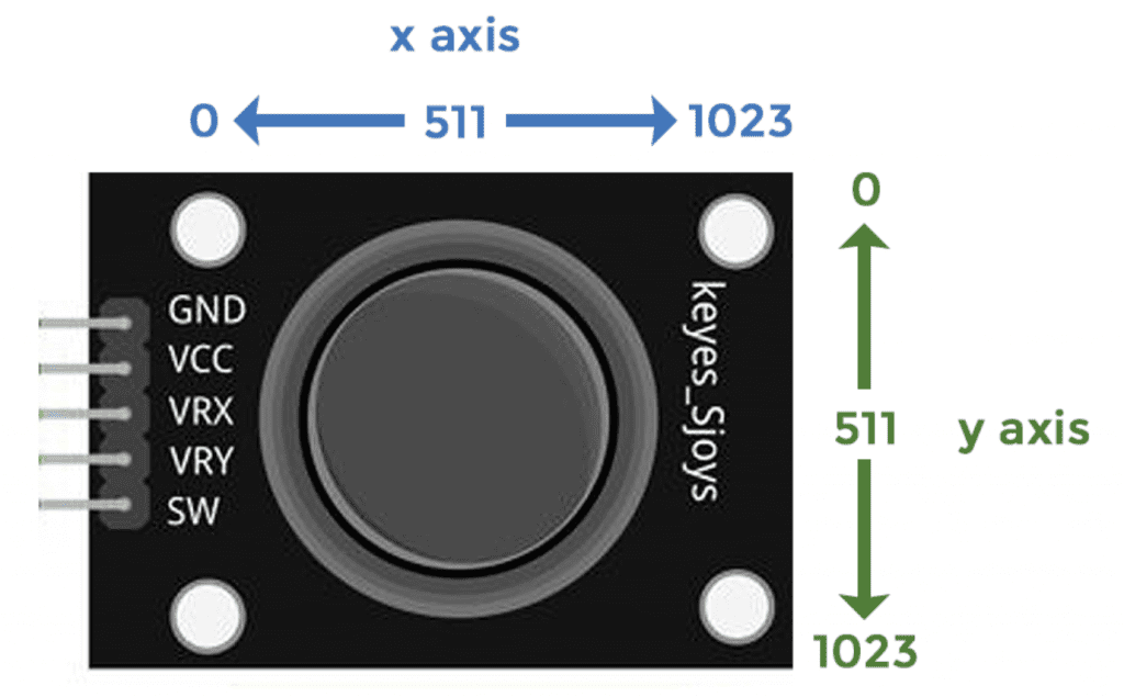
When you pull the stick back, the Y axis output signal increases linearly from 511 to 1023. When you push the joystick up, the value decreases from 511 to 0. So the Y axis travels the full range from 0 to 1023.
The same thing happens with the X axis. Moving the stick all the way to the right increases the X axis output from 511 to 1023. And moving it to the left decreases it from 511 to 0.
The push button switch is digital, and when you press it the value goes from high to low.
How to Connect a PS2 Joystick to the Arduino
These are the parts you will need:
Use the wiring diagram below to connect the PS2 joystick to the Arduino:
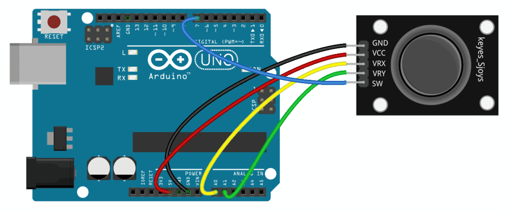
Programming the PS2 Joystick for Raw Data Output
The sketch below will print the raw analogRead() values of the joystick to the serial monitor. Once the PS2 joystick is connected to the Arduino, upload this code:
int xPin = A0;
int yPin = A1;
int buttonPin = 7;

void setup() {
  pinMode(buttonPin, INPUT_PULLUP);
  Serial.begin(9600);
}

void loop() {
  int xVal = analogRead(xPin);
  int yVal = analogRead(yPin);
  int buttonVal = digitalRead(buttonPin);

  Serial.print("X = ");
  Serial.print(xVal);

  Serial.print("    Y = ");
  Serial.print(yVal);

  Serial.print("    Button = ");
  Serial.println(buttonVal);

  delay(100);
}
Explanation of the Code
First we declare the pin variables to store the joystick pins. An int variable called xPin is set equal to Arduino pin A0, the pin that’s connected to the joystick’s VRx pin. Another int variable called yPin is set equal to Arduino pin A1, the pin the joystick’s VRy pin is connected to. Then we have a variable called buttonPin. The joystick’s SW pin is connected to digital pin 7 so buttonPin is set equal to 7.
In the setup() section we use pinMode(buttonPin, INPUT_PULLUP) to set the buttonPin as an input with the Arduino’s internal pullup resistor. We don’t need to set the xPin and yPin as inputs since analog pins are automatically assumed to be inputs. Then we initialize the serial monitor.
In the loop() section, we declare a few local variables to store the readings from each joystick axis. The xVal variable is set equal to analogRead(xPin). The analogRead() function will measure the voltage at the xPin (pin A0) and convert it to a number between 0 and 1023. This number will be stored in the xVal variable.
The yVal variable is set equal to analogRead(yPin). The analogRead() function will measure the voltage at the yPin (pin A1) and convert it to a number between 0 and 1023. This number will be stored in the yVal variable.
The buttonVal variable is set equal to digitalRead(buttonPin). The digitalRead() function will measure the voltage detected at the SW pin (high or low) and store the value in the buttonVal variable.
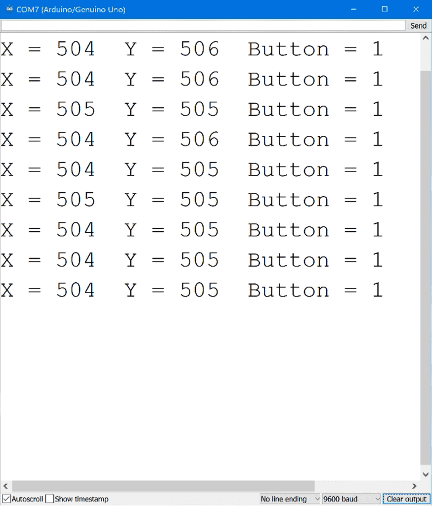
Now we want to print the joystick readings to the serial monitor, so we have a series of Serial.print() functions that print out the values stored in the xVal, yVal, and buttonVal variables. At the end of the sketch, we delay for 100 milliseconds to slow down the output and make it easier to read.
After you connect the joystick and upload the code, open up the serial monitor to see the raw values being printed out:
Controlling LED Brightness With PS2 Joysticks
Now let’s see how to use the joystick’s raw output to control something. In this example project we will set up four LEDs that will increase in brightness when you push the joystick in that direction. LEDs are just an example. They can be replaced by any other device that can be controlled by a pulse width modulation signal (i.e motors and servos).
These are the parts you will need:
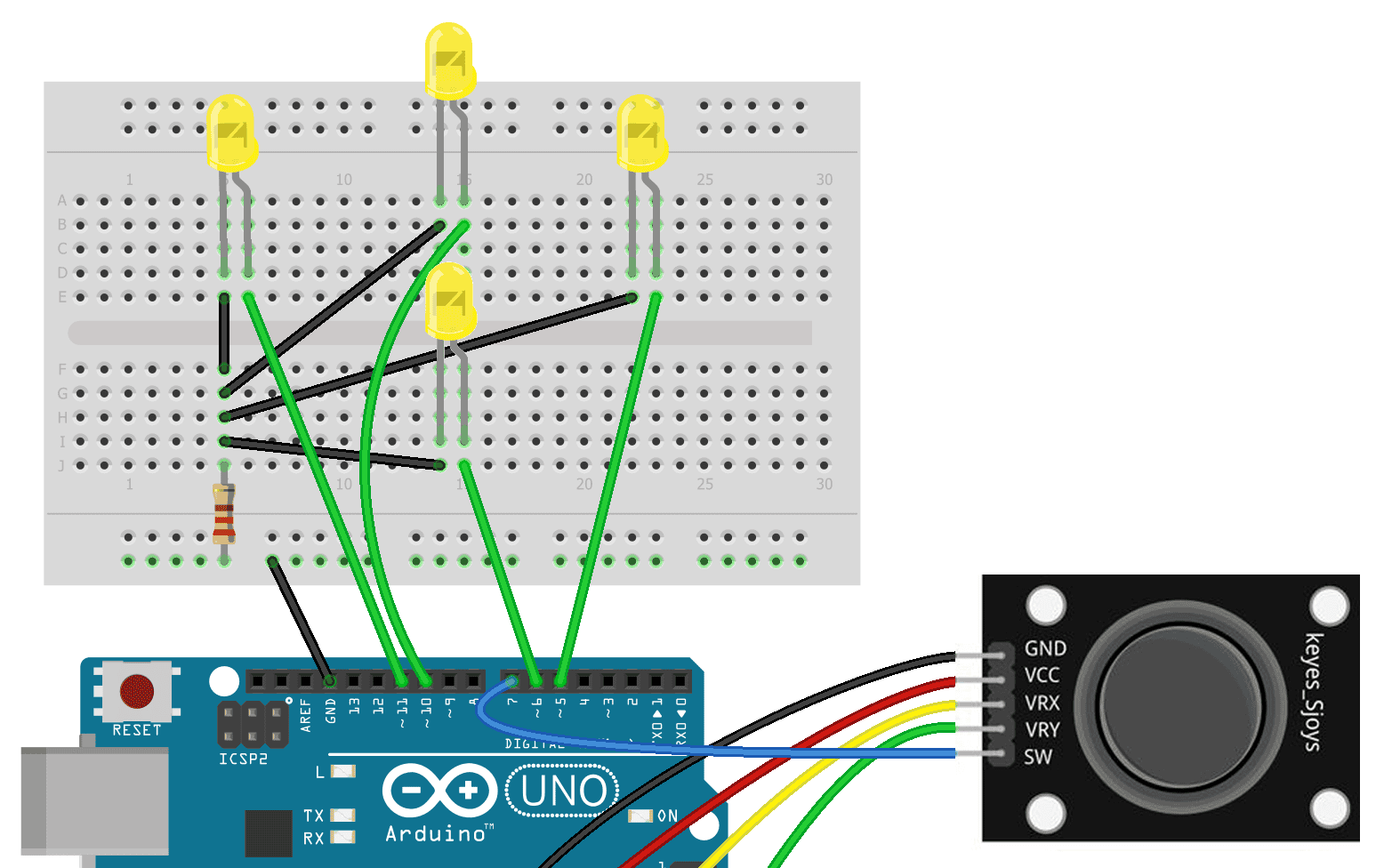
Connect the LEDs and PS2 joystick to the Arduino like this:
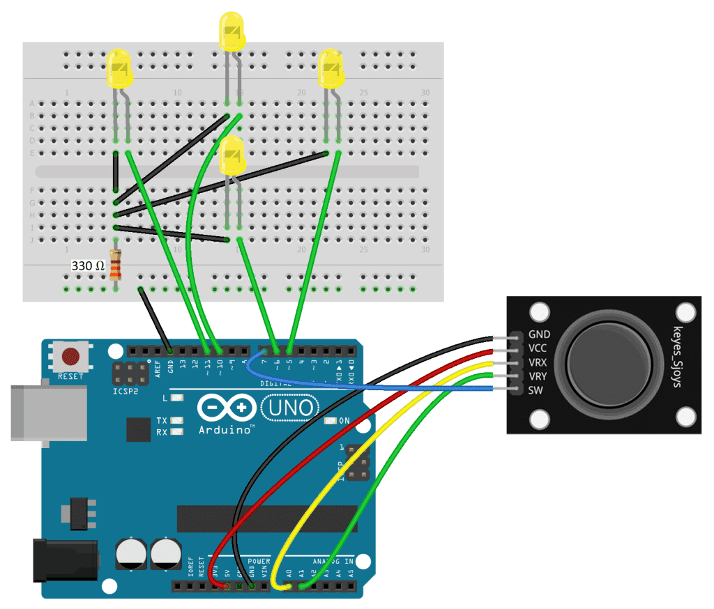
Once the circuit is connected, upload this code to the Arduino:
int xPin = A0;
int yPin = A1;
int buttonPin = 7;

int upLED = 10;
int downLED = 6;
int leftLED = 11;
int rightLED = 5;

void setup() {

  pinMode(upLED, OUTPUT);
  pinMode(downLED, OUTPUT);
  pinMode(leftLED, OUTPUT);
  pinMode(rightLED, OUTPUT);

  pinMode(buttonPin, INPUT_PULLUP);
}

void loop() {

  int xVal = analogRead(xPin);
  int yVal = analogRead(yPin);
  boolean button = digitalRead(buttonPin);

  int upPWM = map(yVal, 511, 0, 0, 255);
  int downPWM = map(yVal, 511, 1023, 0, 255);
  int leftPWM = map(xVal, 511, 0, 0, 255);
  int rightPWM = map(xVal, 511, 1023, 0, 255);

  if (yVal <= 511) {
    analogWrite(upLED, upPWM);
  }

  if (yVal >= 511) {
    analogWrite(downLED, downPWM);
  }

  if (xVal <= 511) {
    analogWrite(leftLED, leftPWM);
  }

  if (xVal >= 511) {
    analogWrite(rightLED, rightPWM);
  }

  if (button == LOW) {
    digitalWrite(upLED, HIGH);
    digitalWrite(downLED, HIGH);
    digitalWrite(leftLED, HIGH);
    digitalWrite(rightLED, HIGH);
  }
}
Explanation of the Code
At the top of the sketch, we declare the xPin, yPin, and buttonPin variables explained in the raw output sketch. Then we declare four variables for the pins connected to the LEDs. There is one variable for each LED – upLED, downLED, leftLED, and rightLED.
In the setup() section, we use the pinMode() function to set each LED pin as an output. We set the buttonPin as an input with the internal pullup resistor.
In the loop() section, we declare the two local variables (xVal and yVal) to store the analog read values of the xPin and yPin. We also declare a variable to store the digital read value of the buttonPin.
We will use pulse width modulation to control the brightness of the LEDs, depending on the analog read value from each axis. We can use the analogWrite() function to send a pulse width modulation signal to each LED pin. But the analogWrite() function can only take inputs between 0 and 255, and the analog read values from the joystick are between 0 and 1023. So we need convert the range of joystick values between 0 and 1023 to a range between 0 to 255.
We can do this with the map() function. The map() function will take a range of integers like 0 to 1023 and convert it to another range of integers like 0 to 255. The map() function takes five parameters:
- First parameter: the variable that stores the numbers you want to be mapped.
- Second parameter: the lower end of the range you want to convert from.
- Third parameter: the upper end of the range you want to convert from.
- Fourth parameter: the lower end of the range you want to convert to.
- Fifth parameter: the upper end of the range you want to convert to.
For example, to map the analog read values from the joystick’s Y axis to a range that can be used by the analogWrite() function, we declare a local int variable called upPWM and set it equal to a map() function. The first parameter of the function is the yVal variable, which stores the analog read value from the yPin.
When the joystick is centered, the analog read value of the Y axis is about 511. When the joystick is pushed up, that value decreases to 0. The up LED will increase in brightness when the joystick is pushed up, so the low end of the input range is 511, and the upper end is 0.
We want the up LED brightness to increase from off to full brightness when the joystick is pushed up. So the low end of the output range is 0 and the upper end is 255. So now, when the yVal variable decreases from 511 to 0, the map() function will convert it to numbers that increase from 0 to 255. And that will be stored in the upPWM variable.
The down LED is similar. We declare another local int variable called downPWM, and set it equal to a map() function. The analog read value of the Y axis is about 511 when the joystick is centered. When the joystick is pulled down, that value increases to 1023. So the low end of the input range is 511, and the high end is 1023. We need that mapped to a value between 0 and 255, so the low end of the output range is 0 and the high end is 255. And that’s stored in the downPWM variable.
For the X axis, we declare two variables called leftPWM and rightPWM to store the mapped analog read values from the xPin. When the joystick is centered, the X axis analog read value is about 511.
When the joystick is pushed to the left, the analog read value decreases from 511 to 0. So the low end of the input range is 511 and the upper end is 0. To make the left LED increase in brightness, the mapped value needs to increase from 0 to 255 when the joystick is pushed left. So the low end of the output range will be 0 and the upper end will be 255. And that will be stored in the leftPWM variable.
For the right LED, the low end is still 511, but since the analog read value increases when the joystick is pushed to the right, the upper end of the output range will be 1023. And that needs to be mapped to a range between 0 and 255.
Next is the code that will control the LED brightness. Each LED has a separate if statement with an analogWrite() function in the body. The condition of each if statement is the range of analog read values that correspond to up, down, left, or right joystick movements.
We only want the up LED to increase in brightness when the analog read value of the Y axis is between 511 and 0. So the first if statement says “if yVal is less than or equal to 511, analog write upLED the mapped range stored in upPWM“.
For the down LED, the yVal variable will increase from 511 to 1023 when the joystick is pushed down, so we use an if statement that says “if yVal is greater than or equal to 511, analog write downLED the mapped range stored in the downPWM variable”.
For the left LED, the analog read value decreases from 511 to 0 when the joystick is pushed left, so we have an if statement that says “if xVal is less than or equal to 511, analog write leftLED the value stored in the leftPWM variable”.
And for the right LED, the analog read value increases from 511 to 1023 when the joystick is pushed to the right, so we have an if statement that says “if xVal is greater than or equal to 511, analog write rightLED the value stored in the rightPWM variable”.
When the push button is pressed, all of the LEDs will turn on at the same time. To program this we use another if statement. Pressing the push button pulls the pin low, so the if statement says “if the button variable equals low, digital write all of the LED pins high”. The body of the if statement has separate digitalWrite() functions for each LED.
After you build the circuit and upload the code, you’ll see that pushing the joystick up slowly increases the brightness of the up LED. When you pull the joystick back, the down LED will slowly increase in brightness. The left and right LEDs should also increase in brightness when you move the joystick left or right. And when you press the switch, all of the LEDs should turn on at the same time.
Hope you found this article helpful. Be sure to leave a comment if you have questions about anything!

What is a PS2 joystick? I was imagining interfacing a PlayStation joystick!
The PlayStation 2 is where this joystick gets it’s name. Probably because the look and feel of the knob is similar…