In this article, we will show you how to use obstacle avoidance and tracking sensors on an Arduino. Obstacle avoidance sensors use infrared light to detect when an object is close to the sensor. They’re a great way to make remote controlled vehicles stop or change course automatically if they come close to hitting an object.

Tracking sensors use infrared light to detect when the sensor is positioned over a dark or light colored object. They are commonly used to guide remote controlled vehicles along a dark colored line on the ground. Let’s take a look at how to set up tracking sensors first, then we’ll come back to obstacle avoidance sensors.
Watch the video for this tutorial here:
Overview of a Tracking Sensor
There are a few different tracking sensors on the market, but the one I’m going to use is the Keyes KY-033 line tracking sensor:
The KY-033 has three pins – one for ground (G), one for Vcc (V+), and one for the signal output (S). The blue LED is the IR transmitting LED, and the black LED is the IR receiving LED. The potentiometer adjusts the sensitivity of the sensor. Turning it clockwise increases the sensitivity, which allows the sensor to be placed farther from the tracking line. Turning it counterclockwise decreases the sensitivity, which allows it to be placed closer to the tracking line.
The Keyes KY-033 has a range from 0.5 cm to 1.5 cm. The IC on the board is an LM393 comparator, which converts the analog signal from the receiving LED into a digital signal that is sent to the sensor’s signal output pin.
How Tracking Sensors Work
White surfaces reflect IR light and dark surfaces absorb IR light. When the tracking sensor is placed over a white surface, the IR light is reflected off of the surface. The reflected IR light is detected by the receiving LED.
But if the tracking sensor is placed over a darkly colored surface, the IR light gets absorbed by the surface. So the receiving LED won’t detect any IR light.
When the receiving LED detects IR light, the sensor outputs a LOW signal. When no IR light is detected by the receiving LED, the sensor outputs a HIGH signal.
How to Connect Tracking Sensors to the Arduino
In this example project, an LED will turn on when the tracking sensor output is HIGH, and turn off when the output is LOW.
Here are the parts you will need:
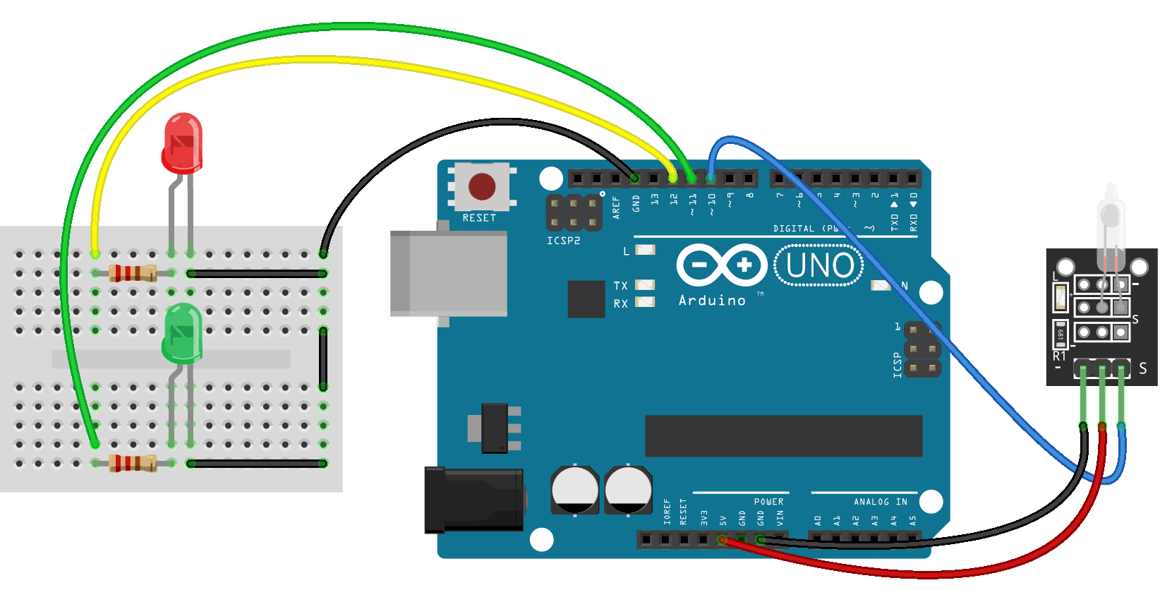
Connect your tracking sensor to the Arduino according to the diagram below:
How to Program Tracking Sensors on the Arduino
Upload this code to the Arduino:
const int sensorPin = 8;
const int ledPin = 10;

void setup() {
  pinMode(sensorPin, INPUT);
  pinMode(ledPin, OUTPUT);
}

void loop() {
  int val = digitalRead(sensorPin);

  if (val == HIGH) {
    digitalWrite(ledPin, HIGH);
  }
  else {
    digitalWrite(ledPin, LOW);
  }
}
Explanation of the Code
At the top of the sketch we declare two variables. sensorPin is set to pin 8, the pin we’ll take the sensor readings from. ledPin is set to pin 10. This is the pin that will power the LED.
In the setup() section we set the pin mode of the sensorPin to INPUT. And the pin mode of the ledPin to OUTPUT.
In the loop() section, the first thing we do is take a digital read of the sensorPin, and store the value in a local variable called val. Now we use an if else statement to control what happens to the LED, based on the reading we get from the sensorPin.
Remember that the tracking sensor outputs a HIGH signal when there is no infrared detected at the receiving LED. In other words, when the sensor is placed over a black surface, the output will be HIGH. When the sensor reading is HIGH, we digital write the ledPin HIGH. When the reading is LOW, we digital write the ledPin LOW.
After the circuit is connected and the code is uploaded, find a black piece of paper or draw a black line on a piece of white paper. When you move the tracking sensor over the white area, the output goes LOW, so the LED should turn off. When the sensor is over the black area, the output is HIGH, so the LED should turn on.
The sensor needs to be placed close enough to the surface for the reflected IR light to reach the receiving LED. You can use the potentiometer to adjust the sensitivity. With greater sensitivity, you’ll be able to position the sensor farther from the surface. Ok, now let’s take a look at obstacle avoidance sensors.
Overview of an Obstacle Avoidance Sensor
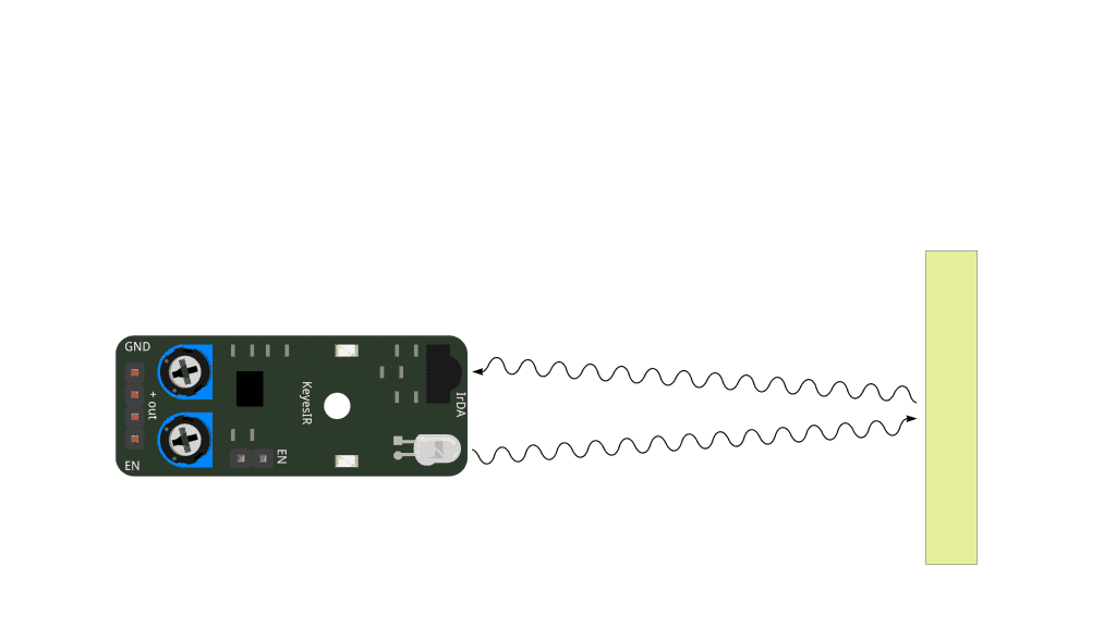
The obstacle avoidance sensor I’m going to use is the Keyes KY-032 obstacle avoidance sensor:
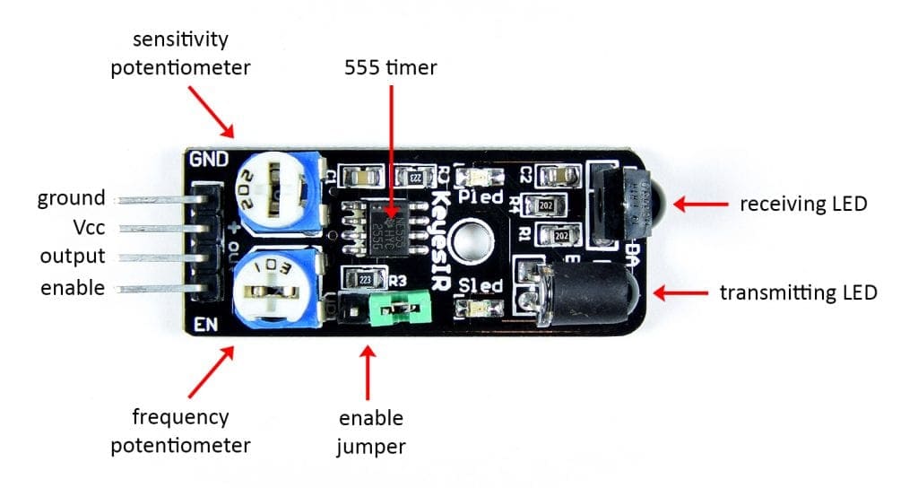
This obstacle avoidance sensor has two potentiometers. The frequency potentiometer adjusts the frequency of the IR light emitted by the transmitting LED. If the obstacle avoidance sensor appears to be picking up interference from another source of IR, try adjusting this potentiometer.
The range of the obstacle avoidance sensor can be adjusted with the sensitivity potentiometer. The sensor has a range from about 1-3 inches. Turning the potentiometer counter-clockwise increases the range, while turning it clockwise decreases the range.
The enable jumper controls the enable function. The enable function lets you turn the sensor ON and OFF with a signal from the Arduino. To use the enable function, remove the pin jumper. Sending a HIGH signal to the enable pin will turn the sensor ON. Sending a LOW signal to the enable pin will turn the sensor OFF.
The 555 timer acts as a comparator that converts the analog signal from the receiving LED into a digital signal that can be detected by the Arduino.
How Obstacle Avoidance Sensors Work
Obstacle avoidance sensors typically have more power than tracking sensors, so they can detect objects at a farther distance. The transmitting LED emits IR light, and the receiving LED detects IR light. The transmitting LED emits infrared light at a constant frequency, set by the frequency potentiometer. The IR light travels through the air, away from the sensor. If an object is in front of the sensor, the IR light hits the object and gets reflected back to the receiving LED.
If an object is within range of the obstacle avoidance sensor, the receiving LED will detect the reflected infrared light and produce an analog electrical signal. That analog signal is sent to a comparator, where it’s converted to a digital signal that can be detected with the Arduino. In the Keyes KY-032 obstacle avoidance sensor the comparator is a 555 timer:
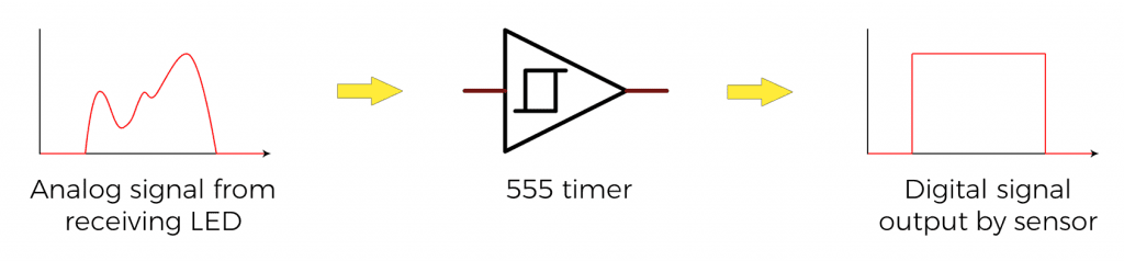
The digital signal output by the sensor is LOW when the receiving LED detects the reflected IR light. The digital signal is HIGH when no reflected IR light is detected by the receiving LED.
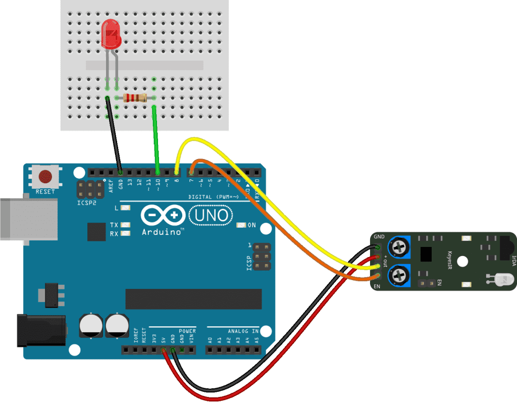
How to Connect Obstacle Avoidance Sensors to the Arduino
In this example project, we’ll use an LED to monitor the output of the sensor. When an object is within range of the sensor, the LED will turn off. When there is no object within range of sensor, the LED will turn on.
These are the parts you will need:
- Arduino Uno
- Jumper wires
- Breadboard
- One 220 Ohm resistor
- One LED
- Keyes KY-032 obstacle avoidance sensor
Here’s how to connect the obstacle avoidance sensor to an Arduino Uno:
How to Program Obstacle Avoidance Sensors on the Arduino
int sensorPin = 8;
int enablePin = 7;
int ledPin = 10;

void setup() {
  pinMode(sensorPin, INPUT);
  pinMode(enablePin, OUTPUT);
  pinMode(ledPin, OUTPUT);
}

void loop() {
  digitalWrite(enablePin, HIGH);

  int val = digitalRead(sensorPin);

  if (val == HIGH) {
    digitalWrite(ledPin, HIGH);
  }
  else {
    digitalWrite(ledPin, LOW);
  }
}
Explanation of the Code
In this sketch, we take a reading from the obstacle avoidance sensor and write the value to an LED. When the output of the sensor is HIGH, the LED will turn on, and when the output of the sensor is LOW, the LED will turn off. We’ll also use the enable function to switch the sensor on and off.
There are three pins in this sketch – the sensor pin, the enable pin, and the LED pin. Each pin is declared as a separate int variable and set equal to the pin number used in the wiring diagram above.
The setup() section is where we set the pin modes for each pin variable. The sensorPin is an INPUT, the enablePin is an OUTPUT, and the ledPin is an OUTPUT.
In the loop() section the first thing we need to do is turn on the sensor, so we digital write the enablePin HIGH. Once the sensor is turned on, we take a digital read of the sensorPin, and store the value in a local int variable called val.
Next we use an if else statement to determine what happens when the sensorPin goes HIGH or LOW. In this case, if the sensorPin reading is HIGH (no object in range of the sensor), we digital write the ledPin HIGH to turn the LED on. Otherwise, we digital write the ledPin LOW (object is within range of the sensor) to turn the LED off.
The output of the sensor goes LOW when there’s an object in range to make it easier to control motors on autonomous vehicles and robots. Motor drivers are usually activated by a HIGH signal, and turned off with a LOW signal. So the sensor’s output will switch off the motor driver if the vehicle gets too close to an object.
Be sure to leave a comment below if you have questions about anything!