Before we get started, please note that in most countries it is illegal to broadcast on FM radio frequencies without a license. The instructions below are for educational purposes only. If you decide to build the FM transmitter circuit below, be sure to follow your local laws and regulations before operating it.

FM Transmitters vs AM Transmitters
One difference between AM and FM transmitters is how modulation is superimposed on the radio signal. In an AM transmitter, the radio signal is modulated up and down in amplitude while the frequency remains constant (amplitude modulation). In an FM transmitter, the amplitude is constant, but the frequency is modulated (frequency modulation).
Another difference between AM transmitters and FM transmitters is the frequency at which they broadcast radio signals. AM radio signals are broadcast between a range of about 550kHz to 1720kHz, while FM signals are broadcast at a range between about 88MHz to 108MHz.
Take a look at our article on How to Build an AM Radio Transmitter if you’re interested in building an AM transmitter.
How to Build an FM Transmitter
The FM transmitter we are going to build works quite well. In my testing, it has a range of about 50 meters. However, the range is highly dependent on the efficiency of the antenna.
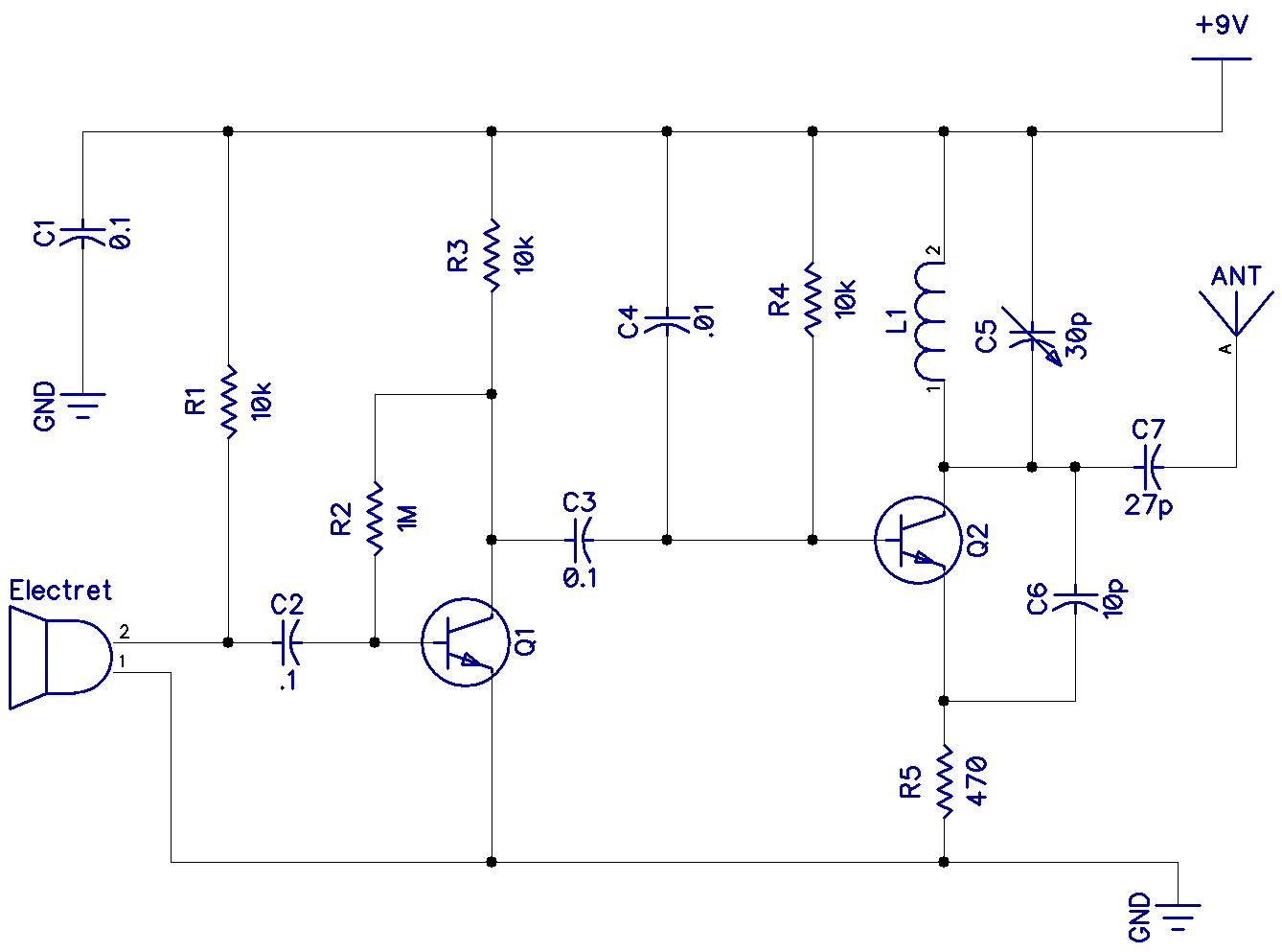
Here is the schematic for the FM transmitter we are going to build:

How the FM Transmitter Works
The circuit is powered by a 9V power supply. Transistor Q1 is a high gain audio amplifier that amplifies the sound detected by the electret microphone. The output of Q1 is fed into the frequency modulating circuit created by transistor Q2, inductor L1, and variable capacitor C5.
This is a very high frequency (VHF) circuit, so you will want to use transistors with a high maximum operating frequency (fT). Use transistors with an fT of at least 200MHz. For example Q1 could be a BC239C bipolar NPN transistor, and Q2 could be a 2N5179 VHF transistor.
0.01uF capacitor C4 grounds the base of transistor Q2, making this a common base circuit. Since there is no phase shift between the emitter and collector in a common base circuit, C6 provides feedback and causes the circuit to oscillate.
The LC circuit created by L1 and C5 determines the frequency of oscillation on the collector of Q2, which can be tuned to a frequency in the FM broadcast band by adjusting variable capacitor C5.
Transistor Q2 also acts as a power amplifier and feeds the frequency modulated audio signal to the antenna through capacitor C7.
How to Build the Antenna
A simple vertical antenna working against a ground plane will suffice. But to be academically perfect, this would entail a sheet of conducting material at least a quarter of a wavelength in radius about the vertical.
How long is a quarter of a wavelength (λ)?
λ = 300/f
Frequency (f) is in MHz.
So for a 100MHz output frequency, the wavelength is:
λ = 300/100
λ = 3m
To find the length of a quarter wavelength:
λ/4 = 75cm
You could also use a dipole antenna, or two wires stretched out in opposite directions, each side being λ/4.
How to Tune the FM Transmitter
The frequency that is transmitted is controlled by the resonance of the tuned circuit formed between L1 and C5. The frequency can be adjusted by turning variable capacitor C5. Capacitor C5 should be in the 10pF to 50pF range.
For example, let’s say we wanted to broadcast an FM radio signal at a frequency of 100MHz. First we need to design a wire coil for L1 that has the same reactance as the capacitor at this frequency.
To calculate the reactance of a capacitor, use this formula:
Xc = 1/2πfC
Xc: Capacitive reactance (Ohms)
f: Frequency (Hz)
C: Capacitance (F)
With variable capacitor C5 adjusted to about 20pF and broadcasting at 100MHz, the reactance of capacitor C5 would be:
Xc = 1 / (2 * π * 1×108Hz * 2×10-11F)
Xc = 79.6Ω
Now that we know the reactance of the capacitor, we can calculate the inductance of L1 that will provide 79.6Ω of reactance. This formula relates reactance to inductance:
XL = 2πfL
XL: Inductive reactance
f: Frequency (Hz)
L: Inductance (H)
We can rearrange this formula to solve for inductance:
XL = 2πfL
L = XL/2πf
Now we can calculate the inductance of L1 requred to get a reactance of 79.6Ω:
L = XL/2πf
L = 79.6Ω / (2 * π * 1×10⁸Hz)
L = 0.127uH
So the inductance of L1 needs to be 0.127uH for its reactance to match the reactance of variable capacitor C5.
To get this inductance, we will need a wire coil about 12mm long with a diameter of about 9mm, and with five turns of magnet wire.
Thanks for reading and hope this helps you learn more about FM transmitters! Leave a comment below if you have any questions.

Hi! Are the capacitance of the capacitors in microF or in F.
They’re in microfarads, except for the 10p, 27p, and 30p capacitors… Those are in picofarads.
q3 =2n3866 is best
Hello,
In stead of Microphone, I want to use an audio signal generator and in stead of antenna , I want to use oscilloscope .
Do these need any change in circuit ?
Thanks
In the text it is said “0.01uF capacitor C4 grounds the base of transistor Q2, making this a common base circuit.”
I don’t quite understand this. The C4 connects the base of the transistor to the +9V supply voltage. It does not connect it to the GND terminal at the bottom of the diagram. Thus while it looks like a common base circuilt (that is, “base” being the common terminal between the input and output circuits of the oscillator), the term “ground” seems to be wrong.
Could you explain this a little more?
For the AC signal Plus and GND are the same since the battery is a voltage source with low impedance
Thanks. Is it correct to assume that this circuit would work precisely in the same manner if C4 would connect to the GND instead?
No, the capacitor C4 must be in paralell with a resistor (in this case the basis DC bias resistor R4) to make a low pass filter, since only the radio frequency must be grounded, not the audio frequencies from the microphone.
Why is there the resistor R1? What does it do?