In the first article in this series on op-amps, we learned how op-amps work and how to build amplifier circuits with them. In the next article, we will look at non-linear applications. In this article, we are going to look at some more useful stuff we can make with them, concentrating on linear applications. Linear applications are where the output of the op amp is related to the input in a straight line, such as in an audio amplifier.

Choosing an Op-Amp
For 90% of the time, you can substitute an op-amp in the circuit you are using with anything that you have on hand. I only keep a few different types of op-amps (about six) in stock. I prefer a FET input type such as an LF441 single op-amp, LF442 dual op-amp, and LM324 quad op-amp. They are all suitable for single or dual power supply applications.
Single and Split Power Supplies
When I began using op-amps, I found this confusing and frustrating—I would find a particular circuit I wanted in a book but was put off if it had a dual supply and I wanted to run it off a battery. So here is the way to do it.
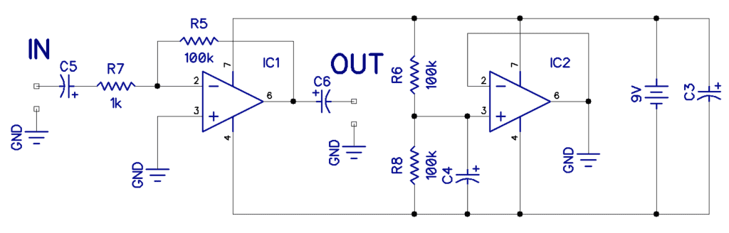
Obviously, you could use two 9V batteries and connect them in series, the center point becoming the ground, but this is messy and expensive. A better way is to use a second op-amp and generate a virtual common, as shown in the schematic below.
The Inverting Amplifier
Shown below is the schematic for an inverting amplifier.
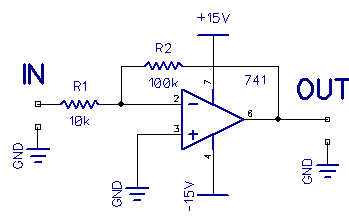
If you feed 0.1V in, you get -1V out. If you feed an AC signal in, the output is 180 degrees out of phase with the input. The input impedance is roughly equal to resistor R1.
The gain of an inverting amplifier is simply R2/R1, in this case, 10X. To minimize offset, we could take pin 3 to ground via a series 10k resistor.
The Non-Inverting Amplifier
Shown below is the counterpart of the previous circuit, the non-inverting amplifier.
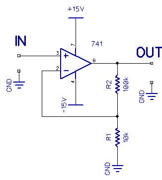
In a non-inverting amplifier the gain is calculated with this formula:
A = (R1 + R2) / R1
In the circuit above, the gain is 11X.
The output is in phase with the input, but the real feature here is that the input impedance is very high, and can be made even higher if you use a FET input op-amp.
The Voltage Follower
The circuit below is a special case of the non-inverting amplifier.
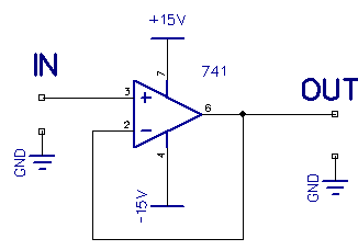
Here, the output voltage is equal to the input voltage. You may well ask, “so, what’s the point?”
It is this: the input impedance is very high, and the output impedance is very low. This makes it most suitable as a buffer stage where you want to isolate one circuit from another, for example, in filter applications.
The Differential Amplifier
Shown below is a differential amplifier.
Differential amplifiers amplify the difference in voltage between the -ve and +ve inputs. Differential amplifiers can be used to detect tiny voltage differences across a circuit. The voltage at one input is subtracted from the other and then amplified. Here all the resistors are the same, so the gain is one.
The Integrator & Differentiator
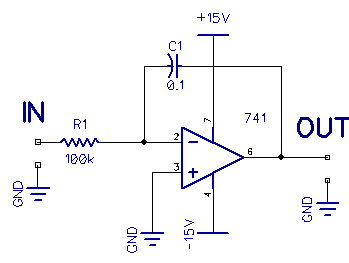
This circuit is an integrator:
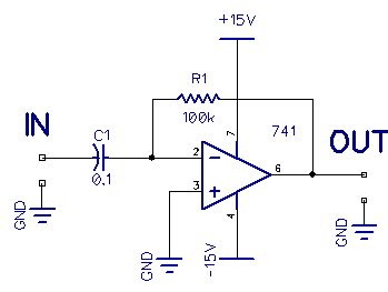
This circuit is a differentiator:
Big math words, you might say, and this is true, but where would you need such circuits?
Let’s say you wanted to count acorns falling from a tree. You could build a circuit with an integrator and an electret microphone, so that every time an acorn fell, a blip would occur in the audio signal. The integrator detects those blips and accumulates them until you reset it.
An integrator will generally have a FET across capacitor C1 to discharge it periodically. But what would happen if you fed a square wave into the integrator?
When the square wave goes high, C1 charges, and when it goes low, C1 discharges, so what you get is a triangle wave at the output:
The differentiator behaves oppositely, and without delving into the math, the diagram below shows the input and output waveforms for a differentiator:
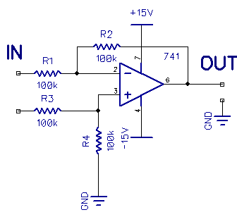
The Summing Amplifier
Shown below is a summing amplifier.
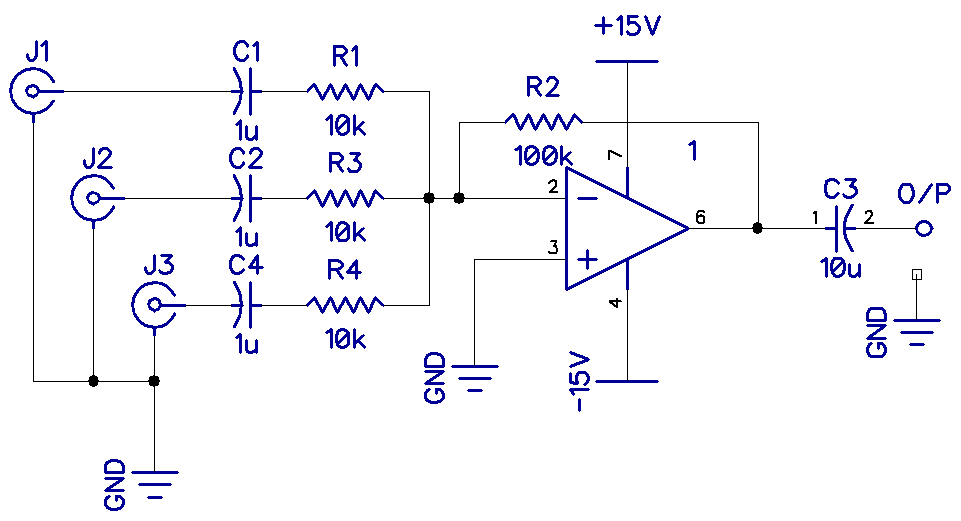
This amplifier will sum multiple inputs into one output. For example, J1 could be a microphone, J2 could be a guitar, and J3 could be a keyboard. The resistors R1, R3, and R4 are linear potentiometers, and the resistance of each relative to R2, would set the level or gain. Resistor R2 could also be a potentiometer acting as a master volume. This circuit contains everything you need for a simple audio mixer.
So now, we have seen some useful applications of linear operation amplifier circuits. In the next article, we will continue the series with Ultimate Guide to Op-Amps – Part 3 (Non-Linear Applications).
Thanks for reading and be sure to leave a comment below if you have a question about anything.