Surely one of the most famous and well-loved IC’s of all time must be the 555 timers, invented by Hans Camenzind of Signetics in 1968. The 555 timer is very stable and easy to use which is probably why it’s so popular.

The 555 timer can do many things, but the main uses are as monostable, bistable, and astable oscillators. In this article, we will look at each of these oscillators in detail, explaining what they’re used for and how to build them..
What’s inside
Here’s a block diagram of the 555 timer’s internal circuitry:
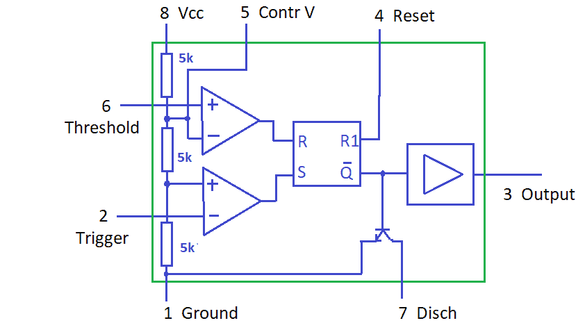
Fortunately, it is not necessary to understand the internal workings to use it successfully. There are two comparators set for 2/3 Vcc and 1/3 Vcc, followed by a reset-able flip flop, followed by an output level driver. The 555 timer got its name from the three 5k resistors in the threshold divider chain from pin 8 to pin 1.
The Pins
| Pin | Description | Function |
| 1 | Gnd | Negative supply pin, ground |
| 2 | Trig | Trigger. When this voltage falls below 1/3Vcc, the output goes high, and timing starts. As long as this is low, the output will remain high. |
| 3 | Out | Output. A push-pull output either high or low capable of driving up to 200mA |
| 4 | Reset | Reset. Resets the timing interval if grounded. If not used, it should be connected to Vcc. |
| 5 | Cont | Control. By applying a V the 2/3 Vcc, timing can be over-ridden. In astable mode, it can modulate the frequency at the output. If it is not used, it should be connected to GND with a 10nF cap. |
| 6 | Thresh | Threshold. When this voltage on the pin is >2/3Vcc, then Out high time ends, sending the output low. |
| 7 | Disch | An open collector can be used to discharge a connected cap; in phase with the output, in bistable and Schmitt mode, it is unused and can act as a second output. |
| 8 | Vcc | Positive supply pin 4.5 to 16V |
Monostable Mode
A monostable circuit likes to stay in one state (high or low) but can be forced to switch to the opposite state for a period controlled by a resistor capacitor (RC) circuit.
This is a schematic for using the 555 timer in monostable mode:
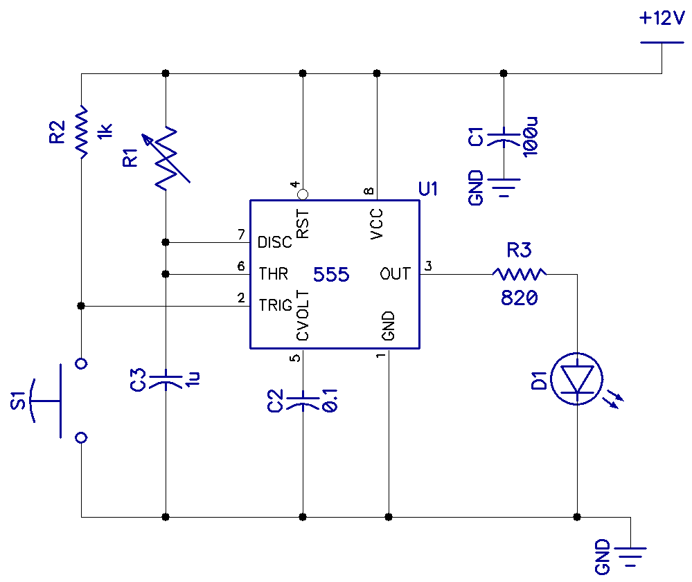
Pin 2 of the 555 timer is kept HIGH by resistor R2, but the instant it goes LOW, the timing period starts, and the output on pin 3 goes HIGH for a period determined by potentiometer R1 and capacitor C3. To calculate the time pin 3 will be HIGH, use this equation:
t = 1.1 * R1 * C3
When this period ends, pin 3 goes LOW again. This is only true for input pulses longer than t. As pin 3 goes HIGH, the instant pin 2 goes LOW, and if pin 2 stays LOW for longer than t, pin 3 will stay HIGH until pin 2 goes HIGH again.
Monostable circuits are very useful for cleaning up a pulse of unreliable length to force it to be a known length, such as a pulse stretcher in a burglar alarm vibration sensor or a momentary push-button circuit.
For a more in-depth look at using the 555 timer in monostable mode, see our article 555 Timer Basics – Monostable Mode.
Bistable Mode
A bistable circuit can exist in one of two states—either on or off. Bistable circuits are commonly used in memory cells, flip flop circuits, and switch debouncers.
This is the schematic to setup the 555 timer in bistable mode:
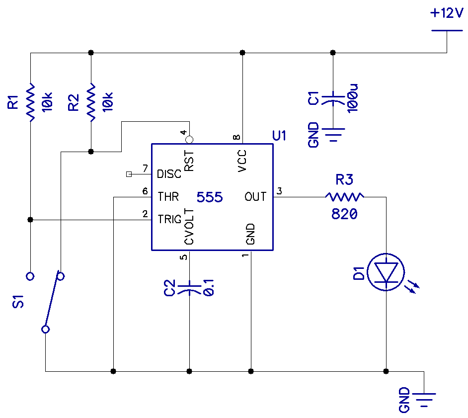
There are no timing capacitors as it is only on or off. Toggle switch S1 will send a LOW signal to either pin 2 or 4, causing the output to change state. It is worth noting that pin 3 will be HIGH on boot up if pin 2 is LOW.
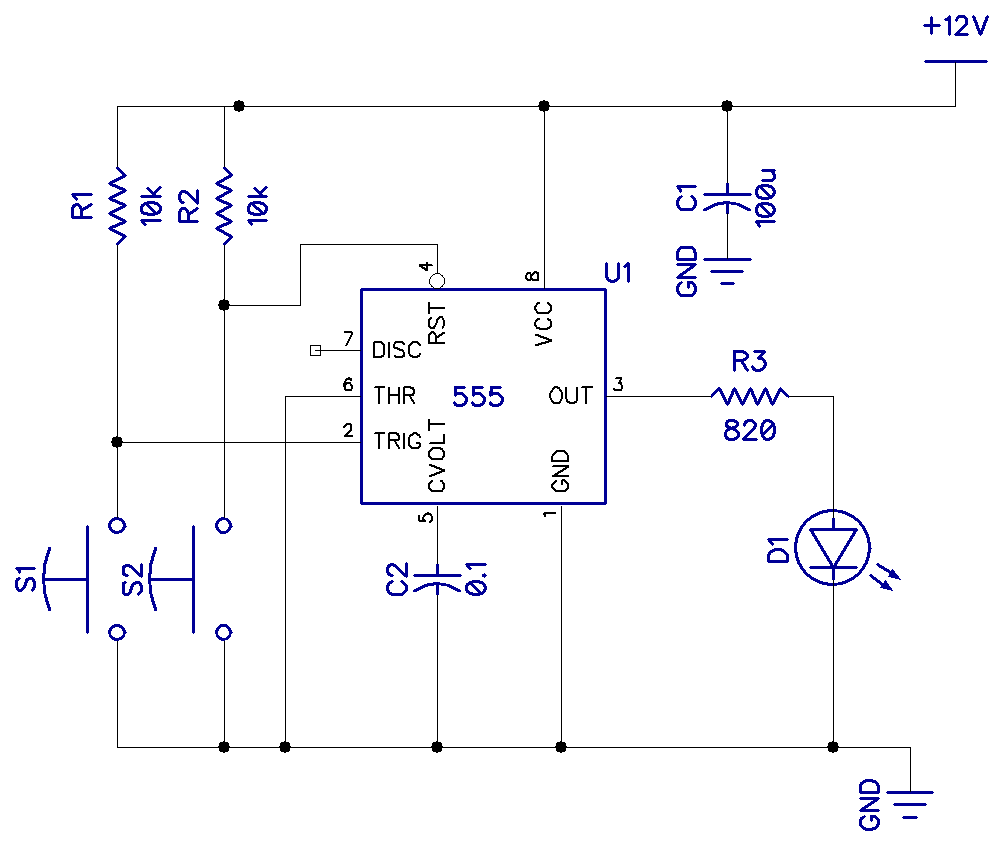
We can also replace the toggle switch with two separate push buttons to achieve the same result:
For more information and example projects using the 555 timer in Bistable mode, see our article 555 Timer Basics – Bistable Mode.
Astable Mode
In astable mode, the 555 timer acts as a square wave oscillator. It can be controlled over a wide range of frequencies with a single capacitor and a variable resistor. Not only that, the duty cycle can be adjusted.
Here is the schematic to connect the 555 timer in astable mode:
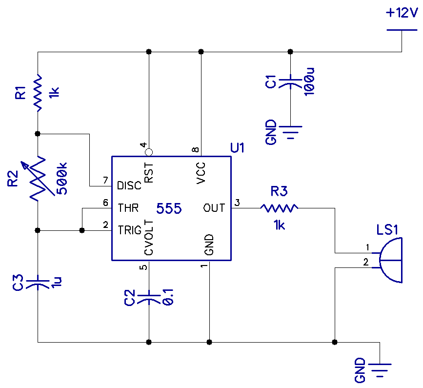
In this circuit, resistors R1, R2, and C3 control the on and off periods’ timing. And the two periods together set the frequency of the output square wave.
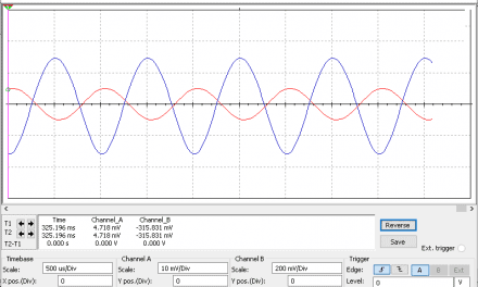
For example, take a look at this diagram:
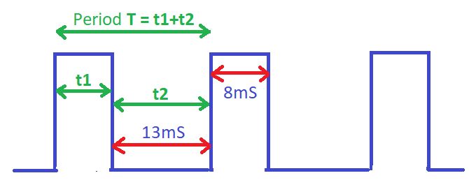
Since t1=8mS and t2=13mS, the period (T) is 8+13 = 21ms. And since the frequency is 1/T = 1/21mS = 47.6Hz.
In the astable circuit above, we can set each of the widths independently using the two equations below:
- Period (T) = 0.7 * (R1+2R2) * C3
- Frequency = 1/T
This will affect the pulse frequency as well as the duty cycle.
For more in-depth discussion about the 555 timer in astable mode, see our article 555 Timer Basics – Astable Mode.
Overall, the 555 timer will be around for a long time because of its great performance, ease of use, and robustness. It is the kind of IC you should keep on hand at all times.
Hope you enjoyed this introduction to the 555 timer. Leave a comment below if you have any questions.


