
In this tutorial, we’ll learn what SPI communication is, how it works, and how to set it up on the Arduino. To demonstrate, we’ll build an example project where an Arduino Uno uses SPI to control an MCP4131 digital potentiometer.

What is SPI?
SPI is an acronym for Serial Peripheral Interface. SPI is a type of synchronous serial communication, which means that data transfer is timed with clock pulses. SPI communication isn’t good for transmitting data over long distances. It should only be used for communication between devices that are less than 10 meters apart.
Parts of an SPI Network
An SPI network consists of a master device and one or more slave devices connected on a bus.
SPI Master Device
The master device sends data to, and receives data from slave devices. There is only one master device in an SPI network.
SPI Slave Device
The slave device receives commands from the master device, and sends data back to the master device. There can be one or more slave devices in an SPI network.
SPI Bus
The SPI bus refers to the wires that connect the master device to the slave devices. Each master and slave device has the following pins:
- Master Out Slave In (MOSI) – the connection for the master device to send data to the slave device
- Master In Slave Out (MISO) – the connection for the slave device to send data back to the master device
- Serial Clock (SCLK) – the line that carries the clock pulse generated by the master device
- Slave Select/Chip Select (SS/CS) – the connection used by the master device to inform the slave device that it will send or request data. The SS/CS pin should be set to
LOWto inform the slave that the master will send or request data. Otherwise, it is alwaysHIGH.
Connecting a Master Device to a Single Slave Device
If there is only one slave device in the network, connecting it to the master device is pretty straightforward. The slave device’s pins are connected to the same pins on the master device. The diagram below shows an example of how to connect a slave device to a master device for SPI communication:
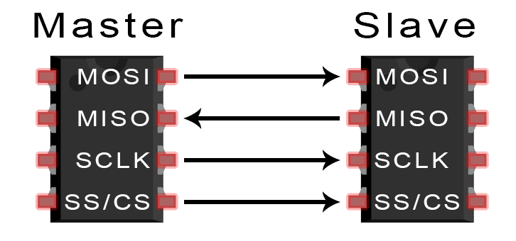
Sending Data to a Single Slave Device
To send data from the master device to the slave device, you first need to set the SS/CS pin on the master device to LOW, and keep it LOW for the duration of the data exchange. This prepares the slave device to send or receive data. Once the SS/CS pin is LOW, the master can send data over the MOSI line and simultaneously produce clock pulses from the SCLK pin.
Connecting a Master Device to Multiple Slave Devices
For an SPI network with multiple slave devices, there are two options for wiring – the independent slave configuration and the daisy chain configuration.
Independent Slave Configuration
As seen in the diagram below, the master device has multiple SS/CS pins. Each SS/CS pin connects to a separate slave device:
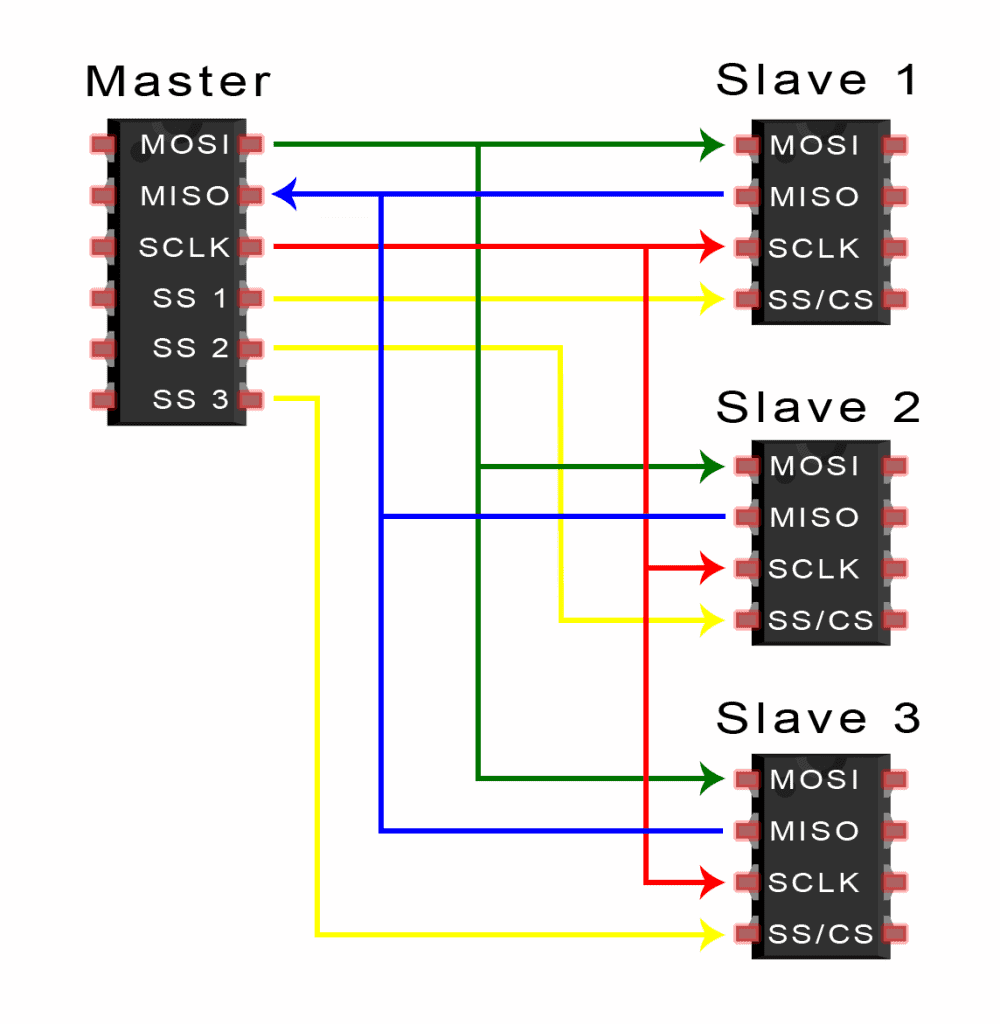
Sending Data in an Independent Slave Configuration
When the master device needs to communicate with a particular slave device, it pulls the SS/CS pin of the slave device LOW. This informs the slave device that the master will send data to it. The master device keeps the SS/CS pin LOW for the duration of the data exchange between the devices.
After the SS/CS pin is set to LOW, the master sends the data over the MOSI line. At the same time, it also sends clock pulses over the SCLK line. If the master device expects a response from the slave device, it will continue to send clock pulses until the data is received at the MISO pin.
Daisy Chain Configuration
In the daisy chain configuration, the master device only needs one SS/CS pin to communicate with all of the slave devices. The diagram below shows how the slave devices are connected to a master device in the daisy chain configuration:
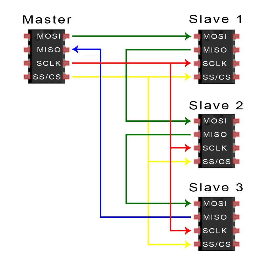
Sending Data in a Daisy Chain Configuration
In the daisy chain configuration, the master device first pulls the SS/CS pin LOW to initiate communication. This will signal all of the slave devices to prepare to receive data at their MOSI pins. The master device then sends data over its MOSI pin to the first slave device in the chain. At the same time, it generates clock pulses at the SCLK pin. The data sent from the master then flows from one slave to the next in the chain. Similar to the other SPI network configurations, the SS/CS pins are kept LOW for the duration of data transmission.
The master needs to send enough clock pulses for the data to reach the last slave device in the chain. If a response from a slave device is expected, the master device will continue to send clock pulses until all of the response data is received at its MISO pin.
For further reading about SPI communication, check out our other article on Basics of the SPI Communication Protocol.
How to Use an Arduino to Control an MCP4131 Digital Potentiometer With SPI
Now let’s demonstrate how to use SPI on an Arduino by building a simple example project. We’re going to use an Arduino Uno to control an MCP4131 digital potentiometer with SPI. We’ll watch changes in the MCP4131’s output resistance on the serial monitor after we send a command via SPI.
The Arduino Uno SPI Interface
The Arduino Uno has built-in hardware support for SPI communication. The SS/CS, MOSI, MISO, and SCLK pins are shown in the diagram below:
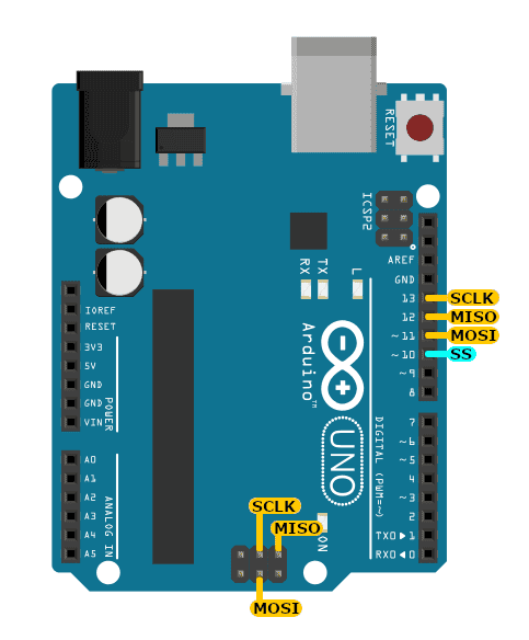
Pins 10-13 are usually used, but there are also MOSI, MISO, and SCLK pins on the ICSP header (near the ATMEGA chip). The MOSI, MISO, and SCLK on pins 11-13 and on the ICSP header are one and the same, so using the ICSP header doesn’t free up pins 11-13 for other purposes.
The MCP4131 Digital Potentiometer
The MCP4131 is basically a resistor network with potentiometer pin outs. We can digitally control the output resistance at pin 6 by sending commands over SPI to pins 1, 2, and 3. Below is a pin diagram for the MCP4131:
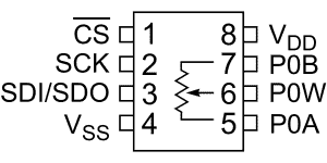
You might be wondering where the MOSI, MISO, and SCLK pins are. Sometimes, the SPI interface pins are labeled differently depending on the device manufacturer. The MCP4131 SPI pins are as follows:
- MISO = Serial Data Input (SDI) at pin 3 (combined with MOSI)
- MOSI = Serial Data Output (SDO) at pin 3 (combined with MISO)
- SCLK = Serial Clock (SCK) at pin 2
You can learn more about the MCP4131 by reading the datasheet.
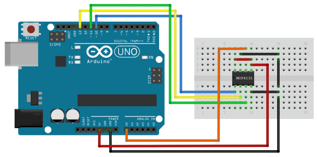
Connecting an MCP4131 to the Arduino With SPI
To build this project, you’ll need the following components:
After gathering all of the components, build the circuit following the wiring diagram below:
If you want to learn more about the Arduino, check out our Ultimate Guide to the Arduino video course. You’ll learn basic to advanced Arduino programming and circuit building techniques that will prepare you to build any project.
The SPI Library
To utilize the Arduino Uno’s SPI interface, we need to use the SPI library. This is a standard library that comes packaged with the Arduino IDE software.
The Code
Once the circuit is connected, upload this code to your Arduino:
#include <SPI.h>

void setup() {
  pinMode(10, OUTPUT); // set the SS pin as an output
  SPI.begin();         // initialize the SPI library
  Serial.begin(9600);
}

void loop() {

  digitalWrite(10, LOW);            // set the SS pin to LOW

  for(byte wiper_value = 0; wiper_value <= 128; wiper_value++) {

    SPI.transfer(0x00);             // send a write command to the MCP4131 to write at registry address 0x00
    SPI.transfer(wiper_value);      // send a new wiper value

    Serial.println(analogRead(A0)); // read the value from analog pin A0 and send it to serial
    delay(1000);
  }

  digitalWrite(10, HIGH);           // set the SS pin HIGH
}
How the Code Works
We add the SPI library with #include <SPI.h> at the beginning of the sketch.
The SPI library only supports the Arduino as a master device. Because of this, pin 10 needs to be configured as an OUTPUT, to avoid conflicts in the operation of the library. We do this by adding pinMode(10, OUTPUT); inside the setup() section.
SPI.begin()
Next we need to initialize the SPI bus. We do this by using the SPI.begin() function inside the setup() section. Calling SPI.begin() sets the MOSI, MISO, and SS/CS pin modes to OUTPUT. It also sets MOSI and SCLK to LOW, and sets the SS/CS pin to HIGH.
The first thing to do before sending data to a slave device is to pull the master device’s SS/CS pin to LOW. In this project, the SS/CS pin is Arduino pin 10. We pull this pin LOW with a digitalWrite(10, LOW); inside the loop() section. This will prepare the MCP4131 to receive commands from the Arduino.
SPI.transfer()
To send commands to the MCP4131, we need to use the SPI.transfer(val) function. The val parameter is the data that we want to send over the SPI. This function also returns the data received from the MCP4131.
According to the MCP4131 datasheet, we need to send the wiper’s register address 0x00, followed by a number between 0 and 128. This number sets the output resistance at pin 6 of the MCP4131. A smaller number sets a lower resistance, and a larger number sets a higher resistance.
In the sketch above, we use a for loop to iterate the wiper’s value from 0 to 128, save the value in the variable wiper_value, then use wiper_value as the argument in the SPI.transfer() function to send it to the MCP4131.
To visualize the output resistance of the MCP4131, we need to read the voltage at the Arduino’s analog pin A0 and print it to the serial monitor. To do this, we use a Serial.println(analogRead(A0)) at the end of the for loop. Next we include a one-second delay to slow down the iteration of wiper_value.
After sending the value stored in wiper_value to the MPC4131, we set the SS pin HIGH to tell the MCP4131 that we are done communicating with it. We do this with digitalWrite(10, HIGH) on the last line of the loop() section.
Project Testing
After you connect the circuit and upload the code above, open your Arduino’s serial monitor to see the voltage detected at Arduino pin A0. The Arduino will continuously send commands to the MCP4131 to cycle the wiper value from 0 to 128. After reaching 128, the value resets to 0, and the process repeats. The value shown on the serial monitor will change from 0 to 1023, depending on the resistance of the MCP4131. When the resistance is high, the voltage detected at analog pin A0 will be low, so the number on the serial monitor will be small. When the resistance of the MCP4131 is low, the voltage at pin A0 will be high, so the number on the serial monitor will be large.
So there you have it. Use the example code and wiring diagrams above as a guide for connecting your own SPI devices to the Arduino. If you have any questions, feel free to leave a comment below.


Ok this is good but how do you get data back in to the UNO via spi? Say I want to send a request from the master and then get some data back? Can you add that information?
I am in possession of an Adafruit FT232H Breakout. I need to have a pc communicate with Arduino or RaspBerry. Some advice?