In this tutorial, we will discuss the purpose of getting the current date and time on the Arduino, what is a Real-Time Clock, what is a DS3231 RTC module and we will build a project using a DS3231 RTC module, a 16×2 I2C LCD and an Arduino Uno.

Why Keep Track of the Date and Time?
Keeping track of the current date/time for an Arduino has many purposes. One use for it is for recording/log purposes. For example, an Arduino Weather Station needs timestamps in recording weather data. Another example is for an Arduino digital clock or calendar. Arduino-based clocks use the current time as a timer for reminders or to execute a scheduled command via the Arduino’s I/O pins. Depending on the project, having a way to get the current date and time is very useful.
How to Get the Current Date and Time on an Arduino
There are several ways to get the current date and time. We can get it from a Real-Time Clock (RTC), a GPS device, or a time server.
- Real-Time Clock (RTC) – A Real-Time Clock, or RTC for short, is an integrated circuit that keeps track of time. It uses a back-up battery to maintain the time in the event that the main power source is removed.
- Global Positioning Device (GPS) – A GPS device communicates with satellites to determine its location anywhere in the world. Its GPS data also contains time data.
- Time Server– A Time Server is a computer on a network that reads the time from some reference clock and distributes it to the network. The clock source of a time server can be another time server, an atomic clock, or a radio clock.
An RTC is a very popular and accurate source of time and date in an embedded system like an Arduino because it has low power consumption.
If you want to learn how to communicate with an internet time server to get the current time and date, please read How to Keep Track of the Date and Time on an Arduino.
The DS3231 Real Time Clock Module
The DS3231 RTC module is a real-time clock module using the DS3231 IC. The DS3231 IC is a very affordable and extremely accurate RTC with an I2C interface. It is very accurate because it uses an integrated temperature-compensated crystal oscillator (TCXO) along with a crystal. To keep track of time even if the main power source is removed, the DS3231 has a backup battery mounted at the back of the module. The chip automatically switches between main and backup power sources when necessary.
The RTC keeps track of seconds, minutes, hours, day, date, month, and year data. It also automatically adjusts for months with less than 31 days and also for leap years. The clock can operate in either 24H or 12H (with AM/PM) formats. There are also two programmable time-of-day alarms and also a programmable square-wave output. Communication with the RTC is done through an I2C interface with a fixed default address of 0x68.
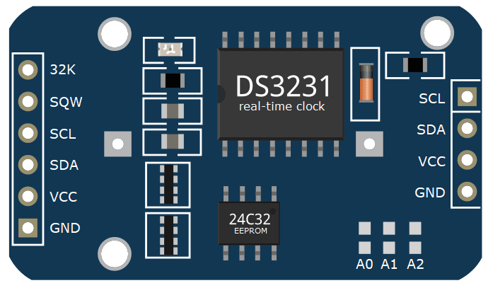
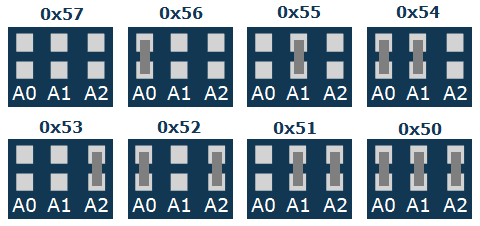
Aside from the RTC chip, this particular module also has a 24C32 EEPROM chip. An EEPROM is a kind of data storage device wherein you can read/write data. The 24C32 has 32 bytes of available data storage space. It shares the module’s I2C bus with the DS3231 and has the default address of 0x57. We can change the EEPROM’s default address by bridging the solder pads indicated by A0, A1, and A2 as shown in Figure 2.
Module Pinouts
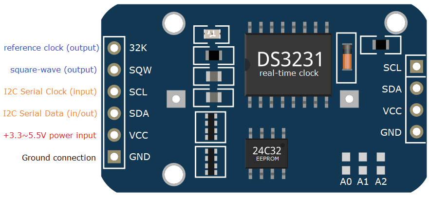
- 32K – outputs from the DS3231 chip a very accurate 32KHz oscillator
- SQW – outputs a square-wave signal from the DS3231 chip. The frequency of the square-wave can be changed between 1Hz, 4kHz, 8kHz, or 32kHz programmatically. this pin can also be used programmed as an interrupt output.
- SCL – input pin for I2C Serial Clock
- SDA – input/output pin for I2C Serial Data
- VCC – power source input pin for the module; can be any voltage from +3.3V to +5.5V DC
- GND – Ground pin connection
- The SCL, SDA, VCC, and GND pins at the right side of the module are connected internally at the left side pins with the same label.
Project: Arduino Calendar Clock
After learning about timekeeping and the DS3231 RTC, it is now time to build a project using the DS3231 RTC. For this project, we will make a simple Arduino Calendar Clock using a DS3231 module, a 16×2 I2C LCD, and an Arduino Uno board.
Components Required
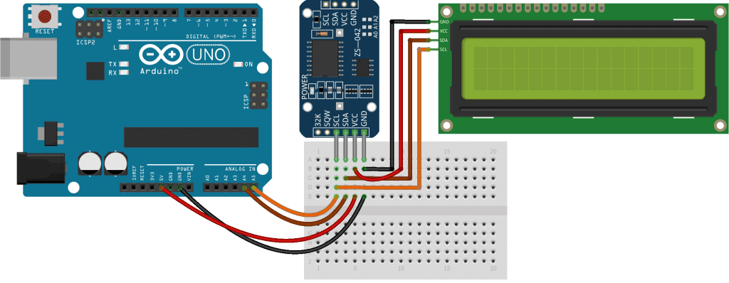
Wiring Diagram
The wiring diagram for our project is shown in Figure 4. Because we are using I2C, all devices share a common bus consisting of only 4 wires.
If you want to learn more about the Arduino, check out our Ultimate Guide to the Arduino video course. You’ll learn basic to advanced Arduino programming and circuit building techniques that will prepare you to build any project.
Arduino Sketch
To make it easy for us to develop the code of our project, we will use libraries and create custom functions to make our code easier to read.
Libraries
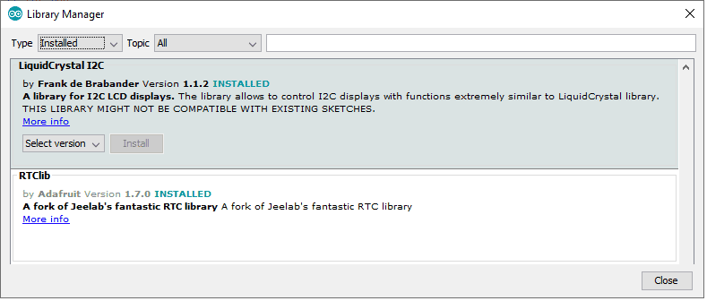
Our project will include the following libraries. See Figure 5 to check which libraries to install using the Arduino IDE’s built-in Library Manager.
Wire.hlibrary for the I2C interface (included in Arduino IDE)LiquidCrystal_I2C.hlibrary (by Frank de Brabander) for the I2C 16×2 LCD module (GitHub link)RTClib.hlibrary (by Adafruit) for the DS3231 RTC module (GitHub link)
The Wire.h library and the I2C protocol were already discussed in previous articles (here and here) and therefore will not be addressed in this tutorial.
To start our sketch, add the abovementioned libraries to our code by using the keyword #include. We will also initialize two objects lcd() and rtc to be used for communicating with the LCD and DS3231 respectively.
#include <Wire.h>                   // for I2C communication
#include <LiquidCrystal_I2C.h>      // for LCD
#include <RTClib.h>                 // for RTC

LiquidCrystal_I2C lcd(0x27, 16, 2); // create LCD with I2C address 0x27, 16 characters per line, 2 lines
RTC_DS3231 rtc;                     // create rtc for the DS3231 RTC module, address is fixed at 0x68
Custom Functions: updateRTC() and updateLCD()
To make our code easier to manage, we will create two custom functions.
The first function we will code is the function updateRTC(). This function will be responsible for asking the user for the date and time and updating the RTC’s internal clock with the user’s input data. After getting the user input, we can update the RTC’s internal clock by using the function rtc.adjust() from the RTCLib.h library. The rtc.adjust() function receives a parameter with type DataTime which it uses to update the rtc’s internal time and date.
/*
   function to update RTC time using user input
*/
void updateRTC()
{

  lcd.clear();  // clear LCD display
  lcd.setCursor(0, 0);
  lcd.print("Edit Mode...");

  // ask user to enter new date and time
  const char txt[6][15] = { "year [4-digit]", "month [1~12]", "day [1~31]",
                            "hours [0~23]", "minutes [0~59]", "seconds [0~59]"};
  String str = "";
  long newDate[6];

  while (Serial.available()) {
    Serial.read();  // clear serial buffer
  }

  for (int i = 0; i < 6; i++) {

    Serial.print("Enter ");
    Serial.print(txt[i]);
    Serial.print(": ");

    while (!Serial.available()) {
      ; // wait for user input
    }

    str = Serial.readString();  // read user input
    newDate[i] = str.toInt();   // convert user input to number and save to array

    Serial.println(newDate[i]); // show user input
  }

  // update RTC
  rtc.adjust(DateTime(newDate[0], newDate[1], newDate[2], newDate[3], newDate[4], newDate[5]));
  Serial.println("RTC Updated!");
}
The second custom function we will create is the function updateLCD(). This function will update or refresh the text displayed on the LCD. Inside this function, we will first get the time and date from the RTC. This is done by calling rtc.now() function which is included in the RTCLib.h library.
The function rtc.now() in our code returns a DateTime data type that contains the current date and time of the rtc. We then assign the data to different variables for additional formatting on the LCD. After assigning the variables, we use the functions lcd.setCursor() and lcd.print() from the LiquidCrystal_I2C.h to position the cursor and to display the text respectively on the LCD. The code below shows how these functions come together to get the rtc time, format the text and display it to the LCD.
/*
   function to update LCD text
*/
void updateLCD()
{

  /*
     create array to convert digit days to words:

     0 = Sunday    |   4 = Thursday
     1 = Monday    |   5 = Friday
     2 = Tuesday   |   6 = Saturday
     3 = Wednesday |
  */
  const char dayInWords[7][4] = {"SUN", "MON", "TUE", "WED", "THU", "FRI", "SAT"};

  /*
     create array to convert digit months to words:

     0 = [no use]  |
     1 = January   |   6 = June
     2 = February  |   7 = July
     3 = March     |   8 = August
     4 = April     |   9 = September
     5 = May       |   10 = October
     6 = June      |   11 = November
     7 = July      |   12 = December
  */
  const char monthInWords[13][4] = {" ", "JAN", "FEB", "MAR", "APR", "MAY", "JUN",
                                         "JUL", "AUG", "SEP", "OCT", "NOV", "DEC"};

  // get time and date from RTC and save in variables
  DateTime rtcTime = rtc.now();

  int ss = rtcTime.second();
  int mm = rtcTime.minute();
  int hh = rtcTime.twelveHour();
  int DD = rtcTime.dayOfTheWeek();
  int dd = rtcTime.day();
  int MM = rtcTime.month();
  int yyyy = rtcTime.year();

  // move LCD cursor to upper-left position
  lcd.setCursor(0, 0);

  // print date in dd-MMM-yyyy format and day of week
  if (dd < 10) lcd.print("0");  // add preceeding '0' if number is less than 10
  lcd.print(dd);
  lcd.print("-");
  lcd.print(monthInWords[MM]);
  lcd.print("-");
  lcd.print(yyyy);

  lcd.print("  ");
  lcd.print(dayInWords[DD]);

  // move LCD cursor to lower-left position
  lcd.setCursor(0, 1);

  // print time in 12H format
  if (hh < 10) lcd.print("0");
  lcd.print(hh);
  lcd.print(':');

  if (mm < 10) lcd.print("0");
  lcd.print(mm);
  lcd.print(':');

  if (ss < 10) lcd.print("0");
  lcd.print(ss);

  if (rtcTime.isPM()) lcd.print(" PM"); // print AM/PM indication
  else lcd.print(" AM");
}
Standard Functions: setup() and loop()
The last phase in completing our code for an Arduino Calendar Clock is to add the standard Arduino functions setup() and loop().
Inside setup(), we will initialize the serial interface, the lcd and the rtc objects. To initialize the serial with a baud rate of 9600 bps, we will use the code Serial.begin(9600);. For the LCD, we need to initialize the LCD object and switch-on the backlight of the display. This is achieved by the codes lcd.init(); and lcd.backlight();. And finally, we add the code rtc.begin(); to initialize the rtc object.
void setup()
{
  Serial.begin(9600); // initialize serial

  lcd.init();       // initialize lcd
  lcd.backlight();  // switch-on lcd backlight

  rtc.begin();       // initialize rtc
}
For the loop() function, we will update the text displayed on the LCD by calling updateLCD();. We will also add the capability to accept user input to update the RTC’s internal clock. If the user sends the char ‘u’ via the serial monitor, it means the user wants to modify the set time and date of the rtc. If this is the case, then we call the function updateRTC(); to handle user input and update the RTC internal clock.
void loop()
{
  updateLCD();  // update LCD text

  if (Serial.available()) {
    char input = Serial.read();
    if (input == 'u') updateRTC();  // update RTC time
  }
}
Our sketch is now complete. Save the sketch as arduino-rtc-tutorial.ino and upload it to your Arduino Uno.
Project Test
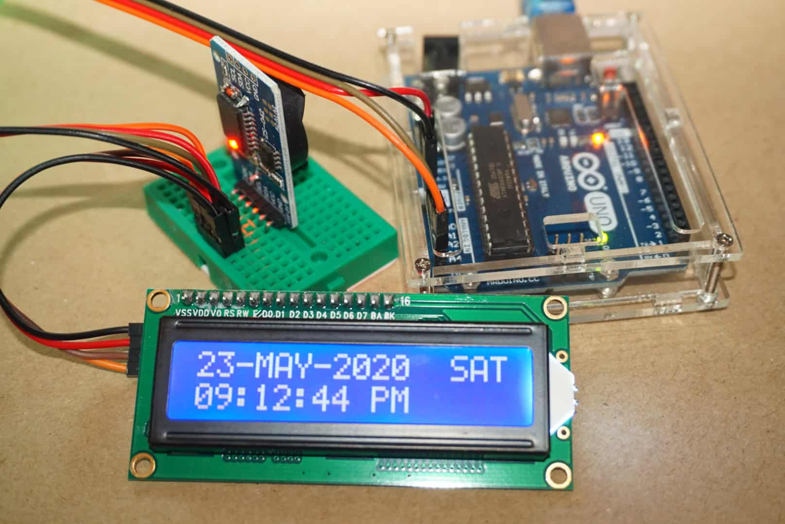
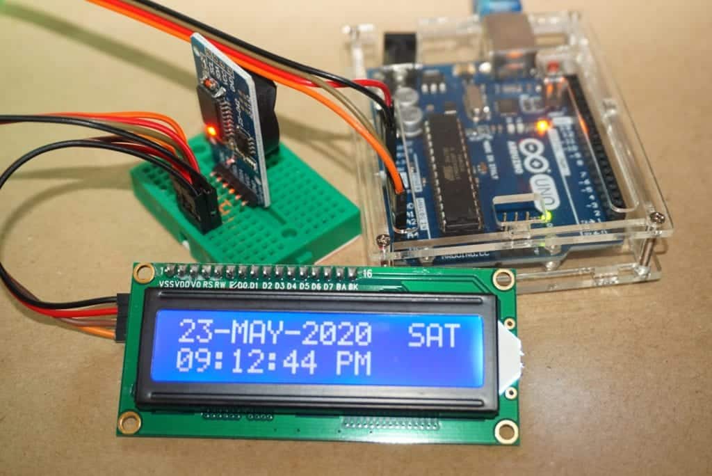
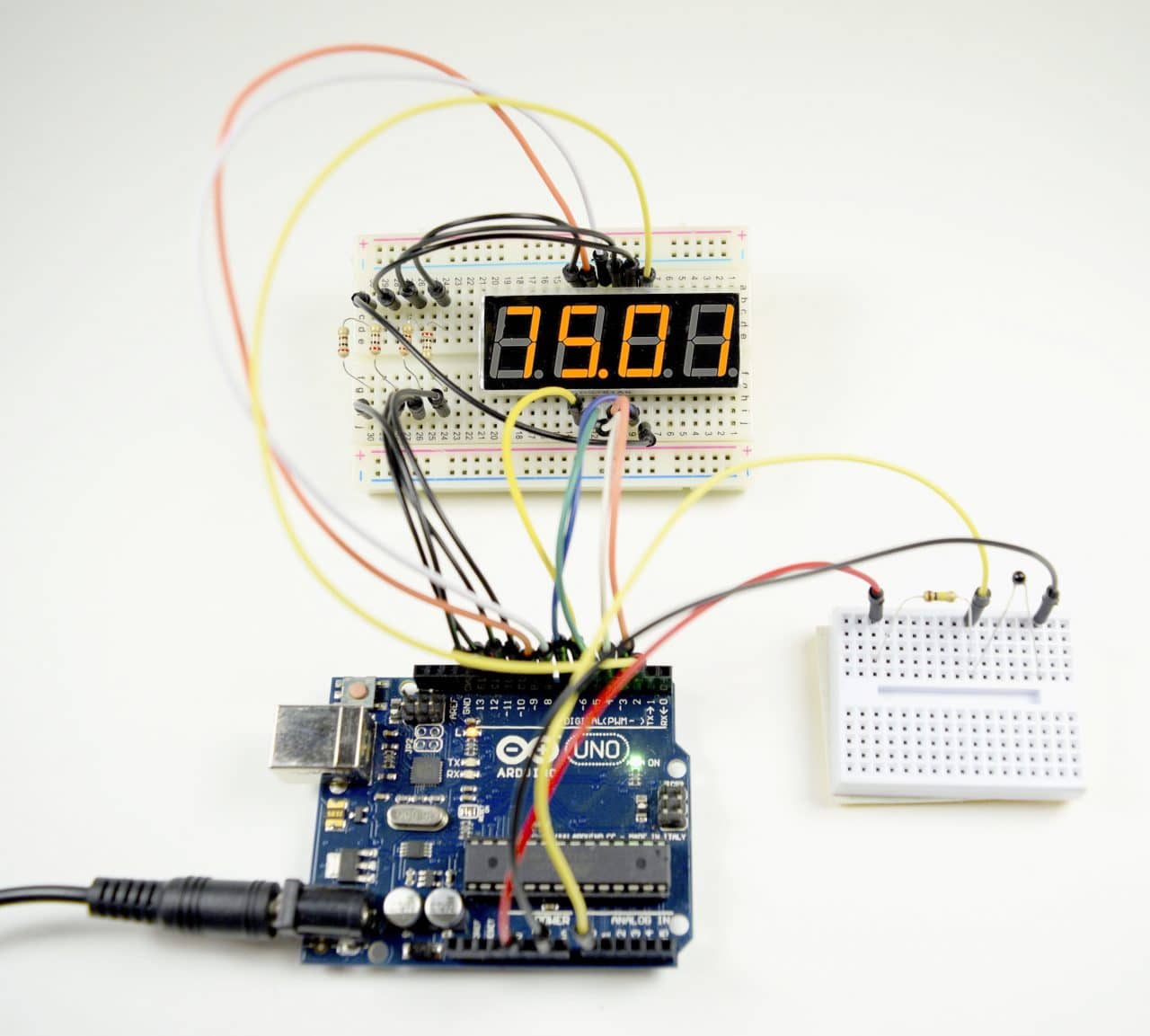
After uploading the sketch, your Arduino Uno should display the date and time on the LCD as shown in Figure 6.
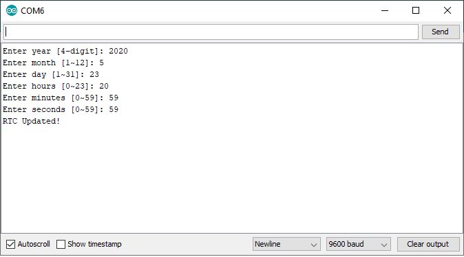
To change the date/time, open your Serial Monitor, and send the letter ‘u’. And then just follow the on-screen prompts to enter the new date and time.
In summary, an RTC module is an easy and inexpensive way to add timekeeping capability to an Arduino based project. This tutorial just showed the basic capability of the DS3231 RTC module. And with more tinkering, you can find lots of uses for this module. Feel free to leave a comment below if you have any questions.

I wonder if I might make a small change to the updateLCD() function, as follows:
void updateLCD()
{
// get time and date from RTC and save in variables
DateTime rtcTime = rtc.now();
/*
* Buffers to format the date and time (on separate lines of the LCD)
*
* Parameters are:
*
| specifier | output |
|———–|——————————————————–|
| YYYY | the year as a 4-digit number (2000–2099) |
| YY | the year as a 2-digit number (00–99) |
| MM | the month as a 2-digit number (01–12) |
| MMM | the abbreviated English month name (“Jan”–“Dec”) |
| DD | the day as a 2-digit number (01–31) |
| DDD | the abbreviated English day of the week (“Mon”–“Sun”) |
| AP | either “AM” or “PM” |
| ap | either “am” or “pm” |
| hh | the hour as a 2-digit number (00–23 or 01–12) |
| mm | the minute as a 2-digit number (00–59) |
| ss | the second as a 2-digit number (00–59) |
If either “AP” or “ap” is used, the “hh” specifier uses 12-hour mode
(range: 01–12). Otherwise it works in 24-hour mode (range: 00–23).
The specifiers within _buffer_ will be overwritten with the appropriate
values from the DateTime. Any characters not belonging to one of the
above specifiers are left as-is.
*/
char dateBuffer[] = “DD-MMM-YYYY DDD”;
char timeBuffer[] = “hh:mm:ss AP”;
// move LCD cursor to upper-left position
lcd.setCursor(0, 0);
lcd.print(rtcTime.toString(dateBuffer));
// move LCD cursor to lower-left position
lcd.setCursor(0, 1);
lcd.print(rtcTime.toString(timeBuffer));
}
As you are alreay using the RTCLib, you might as well use some of the inbuilt functionality to format the date and time! Also, it makes the size of the compiled sketch smaller and could be the difference between getting a sketch to fit, or not, if there was a lot of other code in the required application.
Keep up the good work.
Cheers,
Norm.
Thanks Norm for the improved code. :)
Hi Jan,
sorry! I’ve been messing with your code again! I won;t post it here as the formatting gets weird in the comments section, but help yourself to https://github.com/NormanDunbar/ArduinoClock/tree/master/Sources/ArduinoClock if you wish.
I have amended the updateRTC() function to:
* Validate all user input against minimum and maximum values;
* Allow the user to abort changing the date and time, if necessary;
* Validation of the DateTime created to ensure it is valid re leap years, days in the month etc (using RTCLib);
* Etc.
Thanks for your original code which gave me the impetus to get on and do something!
Cheers,
Norm.
Good job Norm for making an alternative/improved code, our readers will surely appreciate it. :)
Regards,
Jan
Both of you are great… but I’d prefer Jan’s code due to flexibility to arrange name of day and month in other language
All dates default to 19xx regardless of input. e.g 2021 enters as1921
Hi Anthony,
My code, at https://github.com/NormanDunbar/ArduinoClock/tree/master/Sources/ArduinoClock validates the year to make sure it’s between 2000 and 9999. If it is setting as 19xx instead of 20xx, then I wonder if the RTC you are using is somewhat faulty? Perhaps the library in use for the RTC is broken.
I’ll take a look and see. Can you confirm you are using my code or the original please. Thanks.
Cheers,
Norm.
Thank you for your fast response.
I am using your new code.
I can program the RTC to 2021 with other sketches but your code still returns 19xx
The maximum date I can enter is 2099
Hi Anthony,
apologies for the multiple responses. I was advised that the Google Captcha didn’t work and thought I wasn’t able to send a comment. It seems that it worked after all.
I had a look at the RTC library for Arduino. It’s limited to dates between 2000 and 2099, the code specifically checks for this.
I wrote a quick test as I’ve dismantled my LCD clock, but using my code to set the date, I can read back correct dates for this year.
Can you zip up the sketch you are having problems with and attach it to an issue on github for me please? I’ll download it and have a look at yours and see what’s happening as mine is working fine. The URL is https://github.com/NormanDunbar/ArduinoClock/issues – thanks.
I suspect something in the RTC library, as my code simply validates the entered data, with the year being allowed between 2000 and 9999, which I know now is outside the range permitted by the TC library, and then calls “rtc.adjust(newDateTime);” where newDateTime is a DateTime variable (a data type defined in the RTC library) and it’s the library that does the setting of the date and time.
If there’s a problem, is it with dates beyond 2099? If so, it’s being “corrupted” by the library. The library stores the year as an offset from 2000 and it’s stored in an unsigned 8 bit variable (uint8_t). Whatever year is used has 2000 subtracted. There are lots of comments around in the code specifically that years can only be between 2000 and 2099.
Cheers,
Norm.
Here’s a test I did with the latest version of my ClockSetter code from the above GitHub link.
The first test was done with a valid date and time for “right now”, and worked fine:
Enter ‘u’ to update the date and time.
Setting date and time…
Enter year [4-digit] (or -1 to abort) : 2021
Enter month [1~12] (or -1 to abort) : 6
Enter day [1~31] (or -1 to abort) : 2
Enter hours [0~23] (or -1 to abort) : 11
Enter minutes [0~59] (or -1 to abort) : 22
Enter seconds [0~59] (or -1 to abort) : 5
RTC Updated!
02-Jun-2021 Wed 11:22:06 AM
02-Jun-2021 Wed 11:22:07 AM
02-Jun-2021 Wed 11:22:08 AM
02-Jun-2021 Wed 11:22:09 AM
The year is correct, it’s still 2021! The next test was done with years out of range 2000-2099 which are the limits imposed by the RTClib library itself:
Enter ‘u’ to update the date and time.
Setting date and time…
Enter year [4-digit] (or -1 to abort) : 1999 is out of range 2000 – 2099
Enter year [4-digit] (or -1 to abort) : 2100 is out of range 2000 – 2099
Enter year [4-digit] (or -1 to abort) : 2000
Enter month [1~12] (or -1 to abort) : 6
Enter day [1~31] (or -1 to abort) : 2
Enter hours [0~23] (or -1 to abort) : 11
Enter minutes [0~59] (or -1 to abort) : 26
Enter seconds [0~59] (or -1 to abort) : 10
RTC Updated!
02-Jun-2000 Fri 11:26:11 AM
02-Jun-2000 Fri 11:26:12 AM
02-Jun-2000 Fri 11:26:13 AM
02-Jun-2000 Fri 11:26:14 AM
And the years is correctly set to 2000 as requested.
I’m afraid I cannot make my code return a 19xx year.
Cheers,
Norm.
By the way, my RTC is one of these in the code, what’s yours?
RTC_DS3231 rtc;
Cheers,
Norm.
Hi Anthony,
I linked to my “improved” version of the code above and looking at that code, it validates dates so that the year is between 2000 and 9999 so I’m wondering how it’s managing to set a year of 19xx? What code are you using in the sketch?
Cheers,
Norm.
Hi Norman
It would seem that my RTC is faulty.
If I remove the backup battery everything works fine. If I put the battery back in then your code runs the first time but any time after that the year defaults to 19xx regardless of what I enter.
I have replaced the RTC and all is working now.
Many thanks for your time.
Hi Anthony,
glad you got it sorted.
Cheers,
Norm.
Hey bro I got this error on line (lcd.init(); // initialize lcd) its –
Arduino: 1.8.13 (Windows 10), Board: “Arduino Uno”
C:\Users\admin\Desktop\sketch_dec28c\sketch_dec28c\sketch_dec28c.ino: In function ‘void setup()’:
sketch_dec28c:125:8: error: ‘class LiquidCrystal_I2C’ has no member named ‘init’
lcd. init(); // initialize lcd
^~~~
exit status 1
‘class LiquidCrystal_I2C’ has no member named ‘init’
This report would have more information with
“Show verbose output during compilation”
option enabled in File -> Preferences.
Please help because I want to make a arduino clock VERY urgently
Thx bro I solved the problem on my own by replacing init with begin so the new code is lcd.ibegin(); // initialize lcd
And now my clock works perfectly.
Hello, I recently tested this project myself. However, after uploading the code, my screen only lights up and there is no text on it. My wiring is also according to the diagram above(Figure 4), and the LED light on the clock module is also on. Can you tell me how to solve this problem? Thank you!
Oh, I adjust the trim pot control on the back and the text just displayed.
Thank you guys for helping!
I’m not going to be near my Arduino for a while, but I have had this problem on some cheap LCD displays. They need the contrast winding up to make the text appear.
Fit a small trimpot (potentiometer) I use a 10K one, to VCC and GND on the two outer pins, and connect the middle pin to pin 3 on the display. It may be marked as 3, VE or VEE. Now adjust the trimpot until you get text showing up.
You could also force the contrast to maximum by wiring pin 3 on the LCD to VCC. (Or GND depending on which gives maximum contrast on your LCD.)
HTH
Cheers,
Norm.
hello and congratulations for sketch.
Help to have 24 hours format, and have temperature, I have a 20×4 sda scl display. Thank you
Romuald
If you grab my sketch, RTC_uno, from https://github.com/NormanDunbar/ArduinoClock/blob/master/Sources/RTC_Uno/RTC_Uno.ino you can easily change things to 24 Hour format:
* Change the initialisation in 16 by 2 mode to 20 by 4 at line 5. You might also need to change the address of your RTC module, but I think they are all fixed.
* Change the time buffer in line 64 from “hh:mm:ss AP” to “hh:mm:ss” dropping the “AP” off the end of the time string will, according to the specs, use 24 hour format.
Easy!
I haven’t been able to test this as I’m in the process of moving house and most of my stuff is in boxes scattered around the place, sorry.
As for getting the temperature, I think you could add ‘float temp = rtc.getTemperature;’ in updateLCD and print it out on line 3 of your screen. The temperature is in degrees Centigrade by the way.
Apologies again for not being able to test etc, good luck.
Cheers,
Norm.
Yes, great. I was trying to work out how to display a 24 hour clock… Great update. I’ve been doing electronics for 2 months (on and off as a hobbyist) and this project has been the most enjoyable… These updates will make it better. Next to update for temperature and alarm features :-)
Really well-written code with much appreciated custom functions. Thanks a lot!
Great tutorial! I’ve been looking to integrate a real-time clock module into my Arduino project, and your step-by-step guide made it really easy to understand. The wiring diagram was particularly helpful. Looking forward to experimenting with it!